
Laser optical axis adjusting mechanism

A technology for adjusting mechanism and optical axis, which is applied in control/adjustment system, measuring device, surveying and mapping and navigation, etc. It can solve problems such as difficult popularization and application, changing laser optical axis, and high equipment cost

Inactive Publication Date: 2014-03-12
CHONGQING FENGGUO QIYANG TECH DEV
View PDF0 Cites 0 Cited by
  • Summary
  • Abstract
  • Description
  • Claims
  • Application Information

AI Technical Summary

Problems solved by technology

Due to safety factors, the angle of the laser optical axis cannot be changed directly by moving the light source. It is necessary to move the light source through special equipment, but the cost of special equipment is high, and it is difficult to popularize and apply.

Method used


Image

  • Laser optical axis adjusting mechanism

Examples


Embodiment Construction

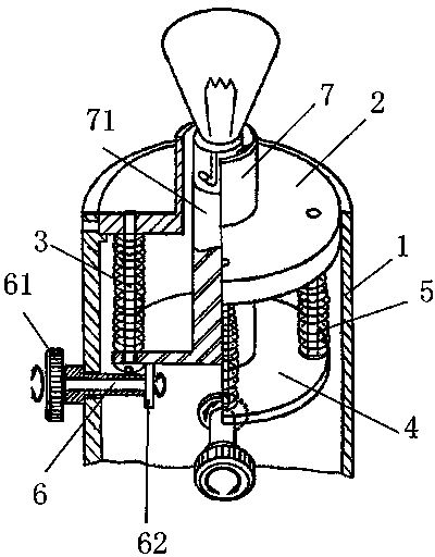
[0009] like figure 1 As shown, the laser optical axis adjustment mechanism of the present invention includes a hollow base 1, on which a support plate 2 is fixed by a limit card, and four support screws 3 are evenly distributed on the bottom circumference of the support plate 2, and the balance plate 4 is floated on the screw head, and a compression spring 5 is arranged between the balance plate 4 and the support plate 2. There are two knobs 61 with rotating rods 6 on the side wall of the base 1, the two rotating rods 6 are perpendicular to each other, and the end of the rotating rod 6 is fixed with a cam 62 in contact with the balance plate 4; The light source support 7 and the light source head 71 are placed in the light source support 7 , and one end of the light source head 71 is fixed on the balance plate 4 .

[0010] Since the cams 62 on the two rotating rods 6 are in contact with the balance plate 4, the cam 62 is rotated through the knob 61, and the balance plate 4 is...


PUM


Abstract

The invention provides a laser optical axis adjusting mechanism. The laser optical axis adjusting mechanism comprises a hollow base, wherein the base is fixedly provided with a supporting plate; the supporting plate is provided with four supporting screws which are distributed uniformly along the periphery; a balance plate is erected on a screw head in a floating manner; a compressed spring is arranged between the balance plate and the supporting plate; the base is provided with two knobs with rotary rods; the two rotary rods are vertical to each other; each rotary rod is further provided with a cam contacted with the balance plate; the supporting plate is provided with a light source support; a light source head is arranged in the light source support; one end of the light source head is fixedly arranged on the balance plate. The two rotary rods are provided with the cams contacted with the balance plate so that the cams are rotated by the knobs; the deflection of the balance plate is caused by jacks of the cams so as to drive the light source head of the balance plate to deflect. The two rotary rods are vertical to each other so that an angle can be adjusted randomly in a horizontal plane and the use requirements are met.

Description

technical field [0001] The invention relates to a mechanical balance mechanism, in particular to an adjustment mechanism for the direction of a laser optical axis. Background technique [0002] The beam of the laser is relatively concentrated, and it can irradiate a long distance without the divergence of the light. It is widely used in ranging and detection. Due to safety factors, the angle of the laser optical axis cannot be changed directly by moving the light source. It is necessary to move the light source through special equipment, but the cost of the special equipment is high and it is difficult to popularize and apply. SUMMARY OF THE INVENTION [0003] The technical problem to be solved by the present invention is to provide a laser optical axis adjustment mechanism, which has the characteristics of simple structure and easy adjustment, and can adjust the laser optical axis safely and conveniently. [0004] In order to achieve the above purpose, the technical sche...

Claims


Application Information

Patent Timeline
Patent Type & Authority Applications(China)
IPC IPC(8): G01C3/02
CPCG05D3/00
Inventor 姜静慧
Owner CHONGQING FENGGUO QIYANG TECH DEV
Learn More