
Corner reflector

A technology of corner reflectors and corner reflectors, applied in the direction of instruments, measuring devices, radio wave measurement systems, etc., can solve the problems of inconvenient pitch adjustment, difficulty in meeting test accuracy and stability requirements, poor stability, etc., and achieve protection of corner reflectors The body, the center of gravity are located reasonably, and the effect of reducing weight

Inactive Publication Date: 2014-03-12
INST OF ELECTRONICS CHINESE ACAD OF SCI
View PDF6 Cites 22 Cited by
  • Summary
  • Abstract
  • Description
  • Claims
  • Application Information

AI Technical Summary

Problems solved by technology

[0006] However, in the process of realizing the present invention, the applicant found that the above-mentioned corner reflector has the following defects: because the right angle cone reflector and the circular turntable are connected by two buckles and a fixed point, resulting in poor stability , the pitch adjustment is inconvenient, and it is difficult to meet the test accuracy and stability requirements

Method used


Image

  • Corner reflector
  • Corner reflector
  • Corner reflector

Examples


Embodiment Construction

[0032] In order to make the object, technical solution and advantages of the present invention clearer, the present invention will be described in further detail below in conjunction with specific embodiments and with reference to the accompanying drawings.

[0033] In the drawings or descriptions in the specification, similar or identical parts all use the same figure numbers. And in the drawings, the shapes or thicknesses of the embodiments may be enlarged, and marked for simplicity or convenience. Furthermore, parts of each element in the drawings will be described separately, and it should be noted that elements or implementations not shown or described in the drawings are forms known to those of ordinary skill in the art. Additionally, while illustrations of parameters including particular values ​​may be provided herein, it should be understood that the parameters need not be exactly equal to the corresponding values, but rather may approximate the corresponding values ​...


PUM


Abstract

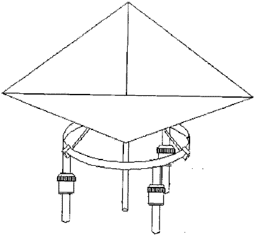
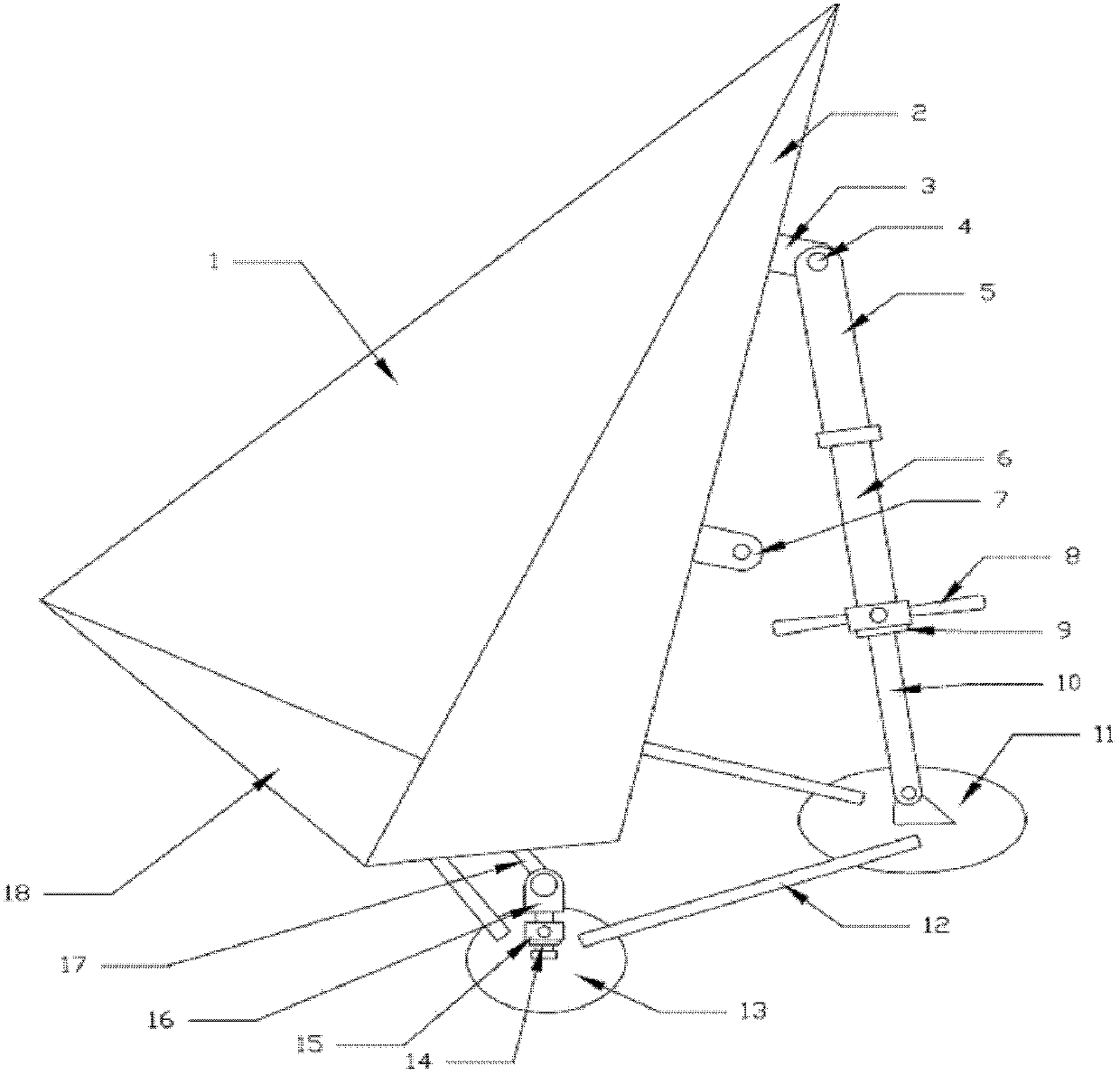
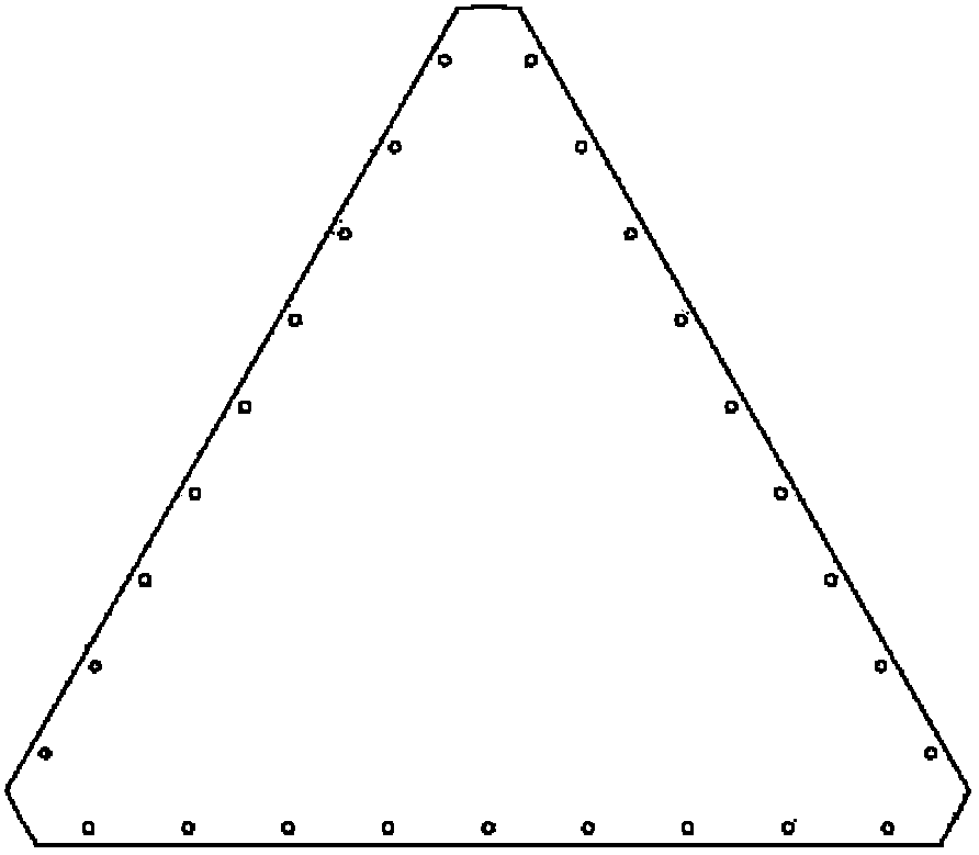
The invention provides a corner reflector which comprises a triangular supporting pedestal, a corner reflector body, and a pitching adjustment mechanism. The triangular supporting pedestal comprises three supporting foundations, a first support, a second support, a third support and a rotating shaft, wherein either two of the three supporting foundations are fixed via angle iron, the first, second and third supports are respectively fixed on the corresponding supporting foundations, and extend upwards along the horizontal plane, and the two ends of the rotating shaft are respectively pivoted to the upper ends of the first and second supports. The corner reflector body is of a triangular cone structure, the bottom surface of the corner reflector body is fixed on a rotating shaft of the pedestal via a welding clamping block, the two side surfaces of the corner reflector body are arranged symmetrically, and multiple pitching adjustment support lugs in different heights are arranged at a connecting position, at the back of the corner reflector body, of the two side surfaces. One end of the pitching adjustment mechanism is hinged to the third support of the triangular supporting pedestal, and the other end of the pitching adjustment mechanism is hinged to one of the multiple pitching adjustment support lugs at the back of the corner reflector body. In the corner reflector, the pitching adjustment support lugs in different heights are used to realize flexible pitching adjustment of the corner reflector body.

Description

technical field [0001] The invention relates to the technical field of radar in the electronic industry, in particular to a corner reflector. Background technique [0002] Because the synthetic aperture radar (SAR) satellite has all-weather and all-time observation capabilities, and has a certain penetration ability to the surface, it plays an important role in disaster monitoring, environmental monitoring, resource exploration and military applications, and is favored by various countries. At present, it has become a hot spot in the development of space earth observation. [0003] In order to ensure that the synthetic aperture radar system has the function of quantitative observation, improve the accuracy of synthetic aperture radar in object classification, target recognition, etc., realize large-scale, all-weather, all-weather dynamic monitoring, and maximize the application benefits, it is necessary to Synthetic aperture radar is calibrated, so establishing a synthetic ...

Claims


Application Information

Patent Timeline
IPC IPC(8): G01S7/02G01S7/40
CPCG01S7/4004G01S7/4078
Inventor 闫国刚郑寿庆陈海斌卢坤洪峻
Owner INST OF ELECTRONICS CHINESE ACAD OF SCI
Learn More