Square-outside circular-inside cavity oil expansion tank for transformer of locomotive

A technology of oil expansion tank, outer square and inner circle, which is applied in the direction of transformer/inductor cooling, etc., can solve the problems of limited utilization of cooling tower space, offset of cooling tower frame center of gravity, and low rigidity of oil expansion tank, etc., to achieve Improved operation and maintenance performance, improved structural rigidity, and a reasonable center of gravity

Active Publication Date: 2014-06-04
湖南美德克斯电气有限公司
View PDF3 Cites 0 Cited by
  • Summary
  • Abstract
  • Description
  • Claims
  • Application Information

AI Technical Summary

Problems solved by technology

[0004] At present, the oil expansion tanks at home and abroad have the following problems: 1. The center of gravity of the cooling tower frame is shifted, which is inconvenient for loading and unloading
2. The space utilization rate of the cooling tower is limited. When the capacity of the transformer of the electric locomotive is increased, the buffer volume is insufficient
3. Due to structural limitations, the rigidity of the oil expansion tank is not too high, and the sealing detection pressure is too high, otherwise it will cause large deformation, so the sealing performance is poor, the oil leakage is serious, and even the machine is broken, causing safety hazards and economic losses to the locomotive.
4. The original cooling fan is suspended and installed outside the oil expansion tank. The air inlet needs to adopt a special sealing structure and sealing material, which requires high precision and high cost.

Method used


Image

  • Square-outside circular-inside cavity oil expansion tank for transformer of locomotive
  • Square-outside circular-inside cavity oil expansion tank for transformer of locomotive
  • Square-outside circular-inside cavity oil expansion tank for transformer of locomotive

Examples


Embodiment Construction

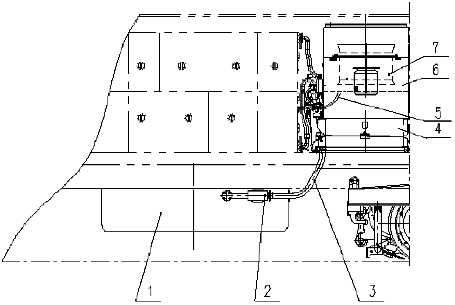
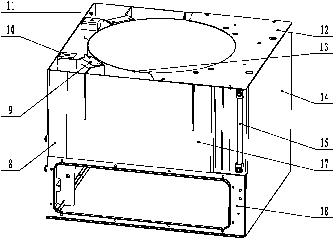
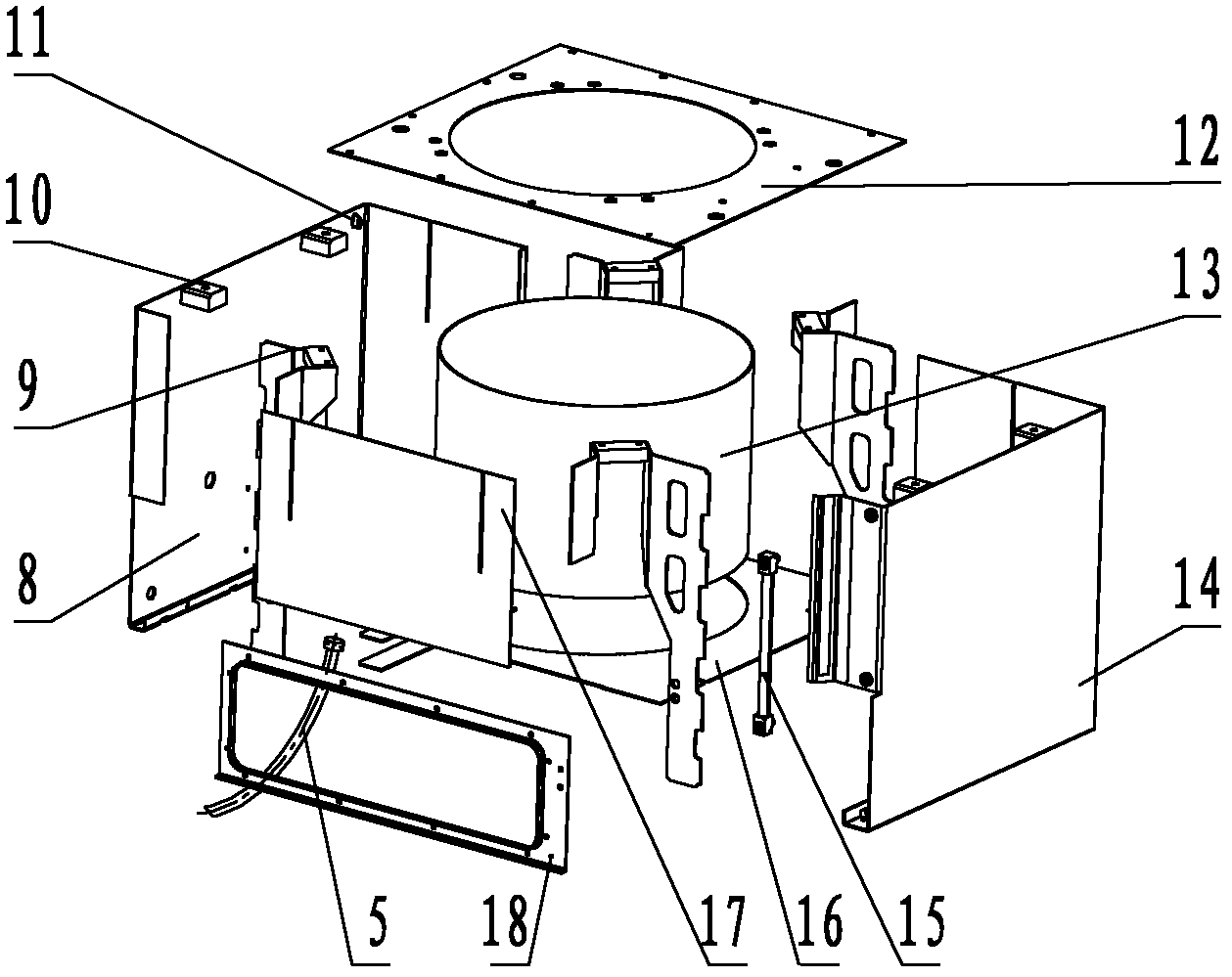
[0018] An embodiment of the present invention will be described in detail below in conjunction with the accompanying drawings. A transformer oil expansion tank device with an outer square inner circle chamber for a locomotive includes a transformer 1, an oil pump 2, a metal hose 3, a radiator 4, a buffer oil pipe 5, and an oil expansion tank. Box 6 and blower fan 7 are characterized in that:

[0019] The oil expansion tank 6 is an outer square inner circle chamber structure, that is, the oil expansion tank 6 is welded into a closed ring cavity container by a left plate 8, a top plate 12, an inner cylinder 13, a right plate 14, a bottom plate 16, and a front plate 17 To constitute the main body of the oil expansion tank, four sets of fan brackets 9 for connecting the fan 7, four sets of lifting nuts 10 for loading and unloading the entire cooling tower and a set of oil level display tubes (15) are welded in the oil expansion tank 6; The oil expansion tank (6) originally arrang...


PUM


Abstract

The invention relates to a square-outside circular-inside cavity oil expansion tank for a transformer of a locomotive. The square-outside circular-inside cavity oil expansion tank comprises a transformer, an oil pump, a metal hose, a radiator, a buffer oil pipe, an oil expansion tank and a fan, and is characterized in that: the oil expansion tank has a square-outside circular-inside cavity structure; fan brackets for connecting the fan, hoisting nuts for assembly and disassembly and an oil level display pipe are welded in the oil expansion tank; the oil expansion tank is communicated with the transformer through the buffer oil pipe; the fan is arranged on the fan brackets in the oil expansion tank; a mounting flange of the fan is connected with a top plate of the oil expansion tank in a sealed mode and a chimney fan of the fan is arranged in a middle circular cavity (inner cylinder) of the oil expansion tank. The oil expansion tank has compact structure and light weight and is low in manufacturing cost and convenient to maintain, the volume of the oil expansion tank is enlarged, the overall size is reduced, the oil expansion tank has uniform structural distribution and reasonable center of gravity and is convenient to assemble and disassemble, a mode of mounting the fan is improved, the sealing requirement of an air inlet of the fan is met, and manufacturing cost of related parts is reduced.

Description

technical field [0001] The invention relates to a transformer oil expansion tank device with an outer square inner circle chamber for a locomotive, which is a medium expansion buffer device for a transformer oil circuit on a railway electric locomotive (including urban rail and subway). Background technique [0002] The main transformer of modern electric locomotives is generally cooled by special transformer oil, which is both an insulating medium and a cooling medium. The temperature change of transformer oil before and after operation generally reaches 60K (from 25°C to 85°C). In northern and plateau areas, the temperature rise is even greater. Affected by thermal expansion and contraction, the volume of transformer oil will change greatly. [0003] In order to provide a buffer for the transformer oil and ensure the pressure stability of the circulation circuit, an oil expansion tank must be connected in series or parallel to the locomotive. The series oil expansion tank...

Claims


Application Information

Patent Timeline
Patent Type & Authority Patents(China)
IPC IPC(8): H01F27/14
Inventor 王先海汪克强王金花邓伟民
Owner 湖南美德克斯电气有限公司
Why Eureka
Try Eureka