Displayer

A display and display panel technology, which is applied in the direction of instruments, refractors, semiconductor devices of light-emitting elements, etc., can solve the problems of inability to realize narrow-frame displays, long light mixing distance, and prolonging process time, so as to save assembly time and process cost , Improve the uniformity of light mixing and reduce the effect of light mixing area

Inactive Publication Date: 2014-03-12
INNOCOM TECH (SHENZHEN) CO LTD +1
View PDF7 Cites 0 Cited by
  • Summary
  • Abstract
  • Description
  • Claims
  • Application Information

AI Technical Summary

Problems solved by technology

Furthermore, the heat dissipation of the direct-type design is high, and the heat dissipation problem needs to be solved by using a metal core printed circuit board (MCPCB), which leads to an increase in cost
In addition, the LED light bar is assembled by screw lock, the assembly process is time-consuming, resulting in prolonged process time
[0004] In order to meet the uniformity of light mixing, the light mixing distance of general displays is long, and it is impossible to realize a display with narrow borders
If it is made into a display with a narrow frame, in order to improve the brightness and darkness of the incident light, it is necessary to increase the number of LEDs, or to design the microstructure at the light entrance of the light guide plate; however, these two methods will increase the manufacturing cost

Method used


Image

  • Displayer
  • Displayer
  • Displayer

Examples


Embodiment 1

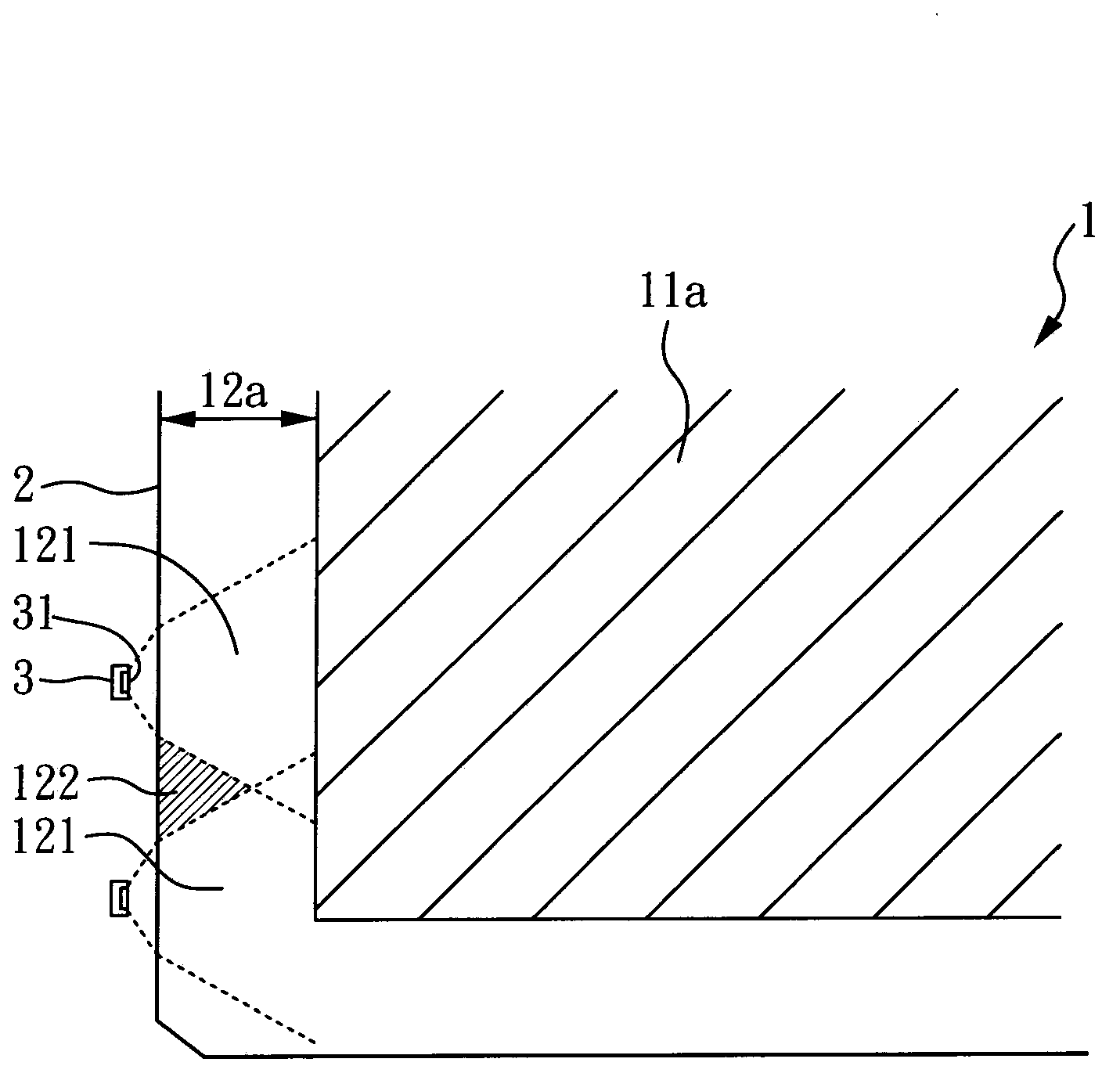
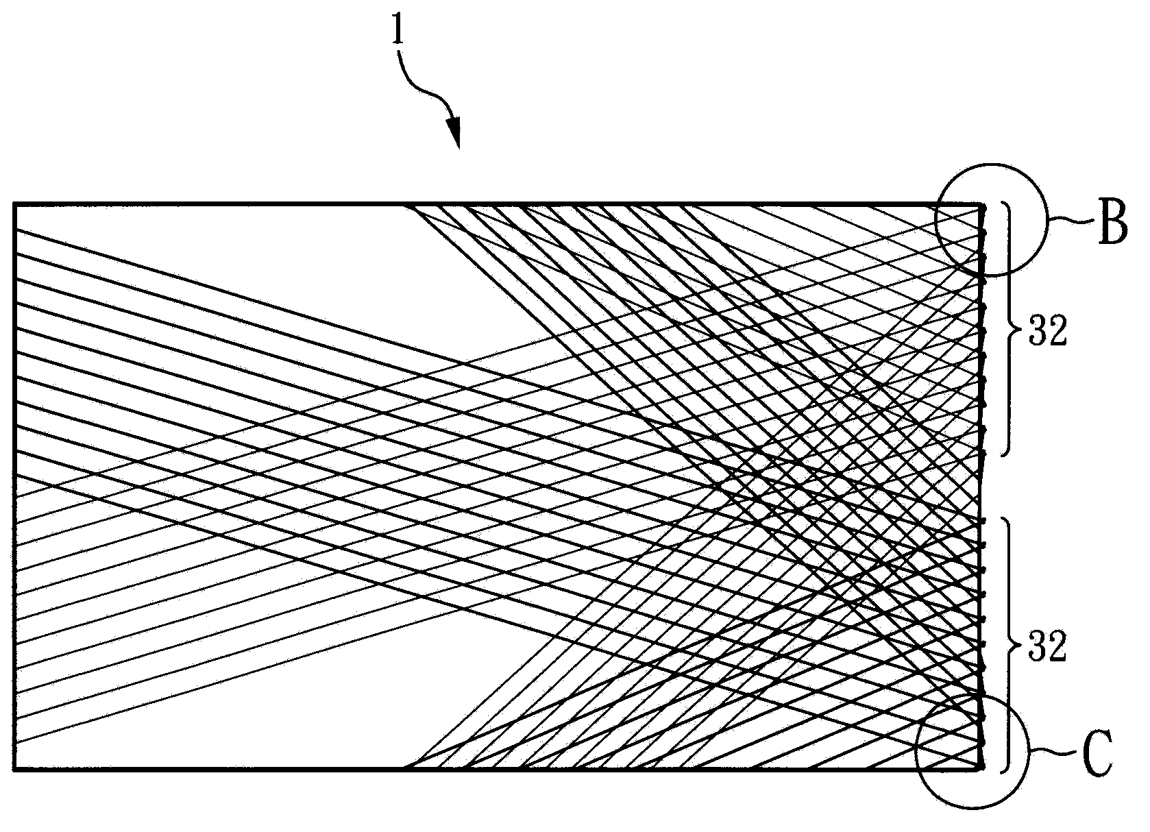
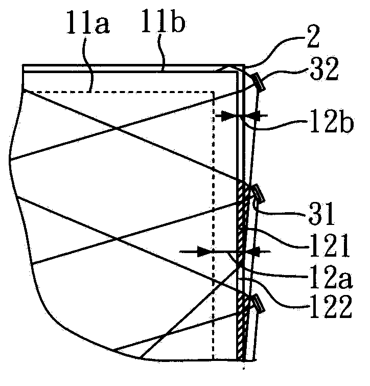
[0039] Figure 2A It is a schematic diagram of a display of an embodiment. This embodiment takes a 31.5" display as an example, but it is not limited thereto. Wherein, the display adopts a single short-side light incident mode, and the light-emitting diode is arranged on a light incident surface of the light guide plate. The light emitting surfaces of the light emitting diodes form an angle with the light incident surface of the light guide plate respectively, wherein the angle range is between 2 degrees and 60 degrees. In this embodiment, the light emitting diodes are divided into two groups, the first group: light emitting The light emitting surface 31 of the diode 32 and the light incident surface 2 of the light guide plate are both inclined downward at an angle of 25°, and the assembly position is relative to the upper right side of the display panel 1, as shown in Figure 2B As shown; the second group: the light emitting surface 31 of the light emitting diode 33 and the l...

Embodiment 2

[0042] Figure 3A It is a schematic diagram of a display. Wherein, the display adopts double-short-edge light-incident mode, and the light-emitting diodes are divided into two groups. The first group: the light-emitting surface 31 of the light-emitting diode 32 and the light-incoming surface 2 of the light guide plate are both inclined downward at an angle of 25°. Relative to the upper right side of display panel 1, such as Figure 3B As shown; the second group: the light emitting surface 31 of the light emitting diode 33 and the light incident surface 2 of the light guide plate are all at an upwardly inclined angle of 25°, and the group setting position is relative to the lower left side of the display panel 1, such as Figure 3C shown. The light emitting diodes 32 and 33 in the two groups are equidistant, and the light emitting surface 31 of the first group of light emitting diodes 32 and the light emitting surface 31 of the second group of light emitting diodes 33 form an...

Embodiment 3

[0045] Figure 4A It is a schematic diagram of a display. Among them, the display adopts a single long side light input mode, and the light-emitting diodes are divided into three groups. The first group: the light-emitting surface 31 of the light-emitting diode 32 and the light-incoming surface 2 of the light guide plate are at an angle of 25° inclined to the right. Relative to the lower right side of display panel 1, such as Figure 4B As shown; the second group: the light emitting surface 31 of the light emitting diode 33 and the light incident surface 2 of the light guide plate are all inclined to the left at an angle of 25°, and the group setting position is relative to the lower left side of the display panel 1, such as Figure 4D As shown; the third group: the light emitting surface 31 of the light emitting diode 34 is parallel to the light incident surface 2 of the light guide plate. Figure 4C shown. The light-emitting diodes 32, 33, and 34 in the three groups are a...


PUM


Abstract

The invention relates to a displayer. The displayer comprises a display panel, a light guide plate and a first light-emitting unit. The light guide plate is arranged on one face of the display panel and is provided with a first light inlet face, and the first light-emitting unit is arranged on the first light inlet face of the light guide plate and comprises a plurality of first light-emitting diodes. An angle is formed between the light outlet face of each first light-emitting diode and the first light inlet face of the light guide plate, and the angle ranges from 2 degrees to 60 degrees.

Description

technical field [0001] The invention relates to a display, in particular to a display that adjusts the angle between the light-emitting surface of a light-emitting diode and the light-incoming surface of a light guide plate to improve the effective light-emitting area and realize narrow frame. Background technique [0002] At present, the design of LED backlight modules can be divided into side-view design (side-view), which is suitable for notebook computers, or top-view design (top-view), which requires a large space for light mixing. The latter is mostly used in large-size panels. on the design. The design of LED backlight modules can be divided into: a side-view design (side-view), which is suitable for small-sized displays such as notebook computers, or a direct-view design (top-view), which requires a large space for light mixing. The latter is mostly used on large displays. [0003] The edge-lit LED backlight unit (BLU) of a large-size display uses a long LED light ...

Claims


Application Information

Patent Timeline
Patent Type & Authority Applications(China)
IPC IPC(8): G09F9/33F21S8/00F21V8/00F21V5/04F21Y101/02F21Y115/10
Inventor 锺昭芳郑雅分张文全
Owner INNOCOM TECH (SHENZHEN) CO LTD
Why Eureka
Try Eureka