Alternately compressing lamination station device

A lamination table and lamination technology, applied in the field of battery cell manufacturing and battery manufacturing equipment, can solve problems such as affecting the quality and accuracy of laminations, affecting lamination speed, poor adaptability, etc., to improve efficiency and save time. , the effect of improving the accuracy

Inactive Publication Date: 2014-03-12
DONGGUAN ARECONN PRECISION MACHINERY
View PDF6 Cites 9 Cited by
  • Summary
  • Abstract
  • Description
  • Claims
  • Application Information

AI Technical Summary

Problems solved by technology

[0002] In the stacking machine of the prior art, there are only one set of pressing claws at both ends of the stacking table, which can only press the pole pieces at one time, and the waiting time is long, which affects the speed of stacking
Or there are two alternate pressing claws at both ends of the stacking table to alternately press the pole pieces, but because the pressing jaws are not paired, they can only press one corner of the pole piece at a time, which affects the quality and accuracy of the stack.
[0003] The lamination table of the prior art drives the pressure claws to move horizontally through the cylinder, which has low motion precision, slow speed, and poor adaptability

Method used


Image

  • Alternately compressing lamination station device
  • Alternately compressing lamination station device
  • Alternately compressing lamination station device

Examples


Embodiment Construction

[0025] In order to further illustrate the principle and structure of the present invention, preferred embodiments of the present invention will now be described in detail with reference to the accompanying drawings.

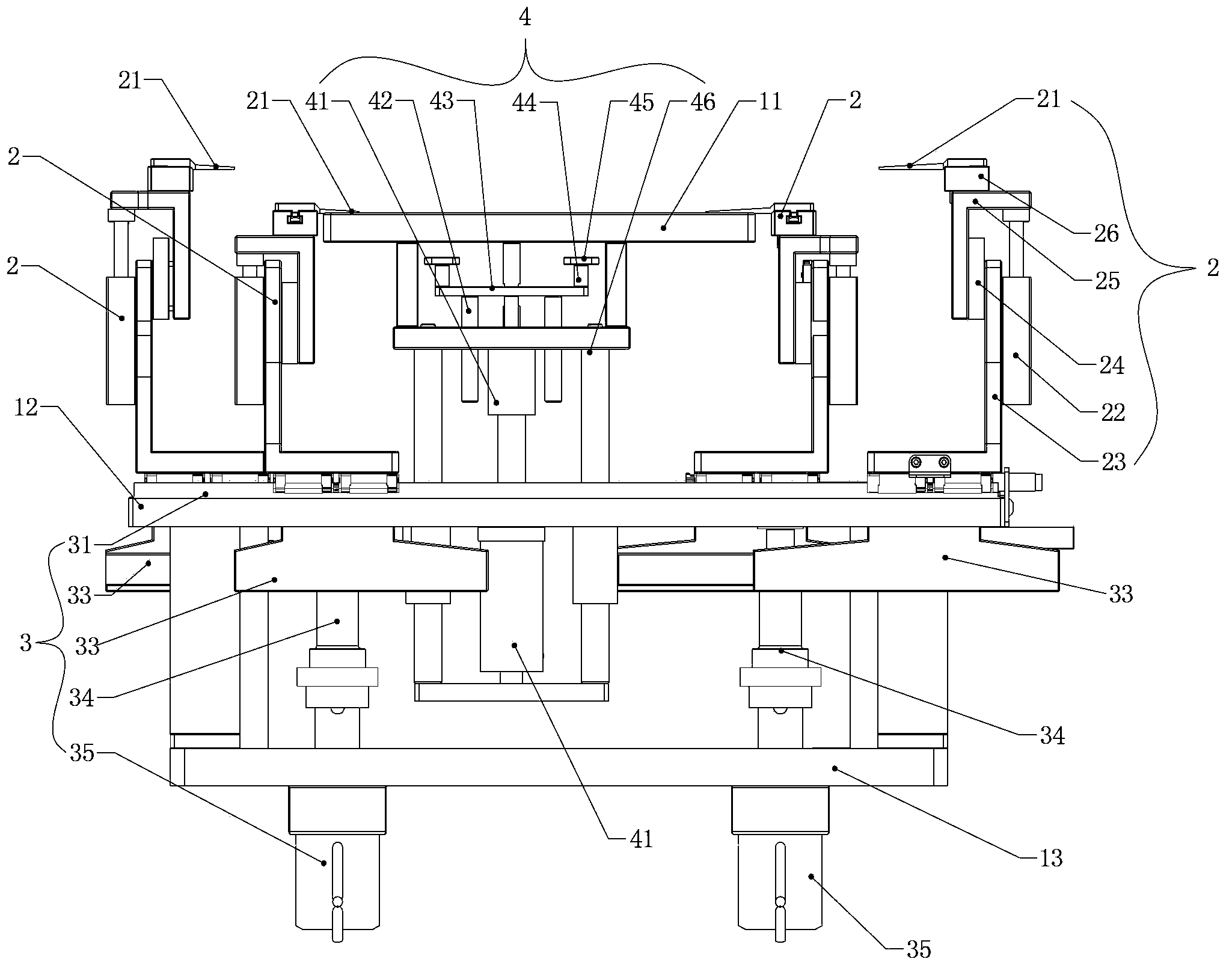
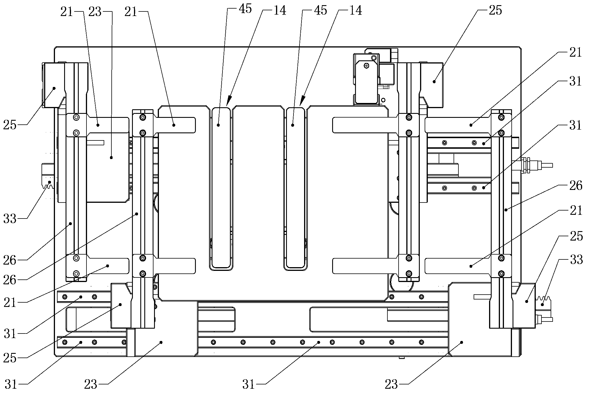
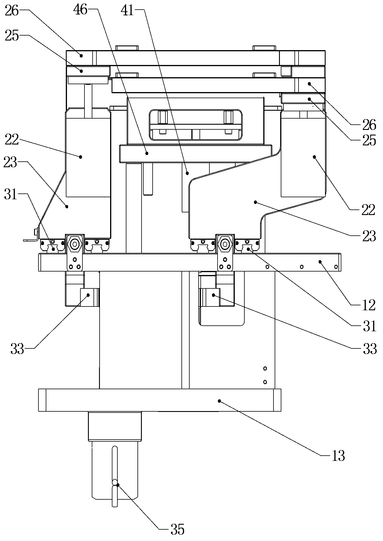
[0026] figure 1 It is the front view of the embodiment of the alternately compacted lamination table device of the present invention, figure 2 is a top view of the structure of this embodiment, image 3 is the left side view of this embodiment.

[0027] The lamination table 1 of the alternate pressing lamination table device embodiment of the present invention has two groups of pressing claw mechanisms 2 that alternately act on the lamination table panel 11 at its two ends. The two sets of moving mechanisms 3 below the lamination table panel 11 respectively drive the two sets of claw mechanism 2 at one end of the lamination table 1 to approach or move away from the lamination table 1 alternately. A replacement mechanism 4 for filling the jaw position groove 1...


PUM


Abstract

The invention provides an alternately compressing lamination station device. The alternately compressing lamination station device comprises four groups of pressing-claw mechanisms distributed at the two ends of a lamination station; every two groups of pressing-claw mechanisms act at one end of a panel of the lamination station alternately; each group of the pressing-claw mechanisms comprises two pressing claws used for compressing two corners of a pole piece, a pressing-claw cylinder which drives the pressing claws to move up and down, and a mobile seat which is used for installing pressing-claw cylinders and the pressing claws and is connected with the mobile mechanism. The device also comprises two sets of mobile mechanisms which respectively drive two groups of pressing-claw mechanisms to close to or leave away the lamination station alternately, wherein each mobile mechanism comprises a horizontal slide rail which is arranged below the panel of the lamination station and is used for installing the pressing-claw mechanisms, gear racks connected with the pressing-claw mechanisms, gear shafts which drive the gear racks to move horizontally, and servo motors which drive the gear shafts to rotate. The device also comprises position filling mechanisms used for filling grooves at clamp claw positions of the panel of the lamination station; and each position filling mechanism comprises a position filling board of which the area is close to that of the groove and a position filling cylinder which pushes the position filling plate. The alternately compressing lamination station device has the advantages that the two groups of pressing-claw mechanisms compress the pole piece alternately; the time is saved; and the lamination efficiency is high.

Description

technical field [0001] The invention relates to the technical field of battery manufacturing equipment, in particular to the technical field of battery cell manufacturing, and in particular to a stacking table device for a cell stacking station. Background technique [0002] In the stacking machine of the prior art, there are only one set of pressing claws at both ends of the stacking table, which can only press the pole pieces at one time, and the waiting time is long, which affects the speed of stacking. Or there are two alternate pressing claws at both ends of the stacking table to alternately press the pole piece, but because the pressing jaws are not paired, only one corner of the pole piece can be pressed each time, which affects the quality and accuracy of the stack. [0003] The lamination table in the prior art drives the pressing jaws to move horizontally through the cylinder, which has low motion precision, slow speed and poor adaptability. Contents of the inven...

Claims


Application Information

Patent Timeline
Patent Type & Authority Applications(China)
IPC IPC(8): H01M6/00H01M10/04
CPCH01M6/005H01M10/0468Y02E60/10Y02P70/50
Inventor 陈保成
Owner DONGGUAN ARECONN PRECISION MACHINERY
Why Eureka
Try Eureka