
Feed feeding vehicle

A feed and frame technology, applied in the field of feed feeding vehicles, can solve the problems of high labor intensity, unsuitability for feed transfer, inflexible transfer and other problems of transfer workers, and achieve compact structure, high power and good operation stability Effect

Active Publication Date: 2014-03-19
JINAN JINGYIDA AGRI & ANIMAL HUSBANDRY MACHINERY
View PDF12 Cites 12 Cited by
  • Summary
  • Abstract
  • Description
  • Claims
  • Application Information

AI Technical Summary

Problems solved by technology

[0002] Feed feeding trucks in the prior art are generally large-tonnage transport vehicles, which are mainly used in large and medium-sized breeding enterprises to transport feed from the outside to the farm. However, due to the large tonnage, large space occupation, and inflexible transfer, they are not suitable The transfer of feed in a relatively small space inside small and medium-sized breeding enterprises still requires manual transfer of feed on the site. The existing problems are that the structure is compact, the work intensity of the transfer staff is high, the efficiency is low, and it is easy to cause feed pollution.
In the prior art, there is no small-scale comprehensive transportation and unloading tool suitable for internal feed transfer in breeding enterprises

Method used


Image

  • Feed feeding vehicle
  • Feed feeding vehicle
  • Feed feeding vehicle

Examples


Embodiment Construction

[0024] In order to better understand the present invention, the embodiments of the present invention will be explained in detail below with reference to the accompanying drawings.

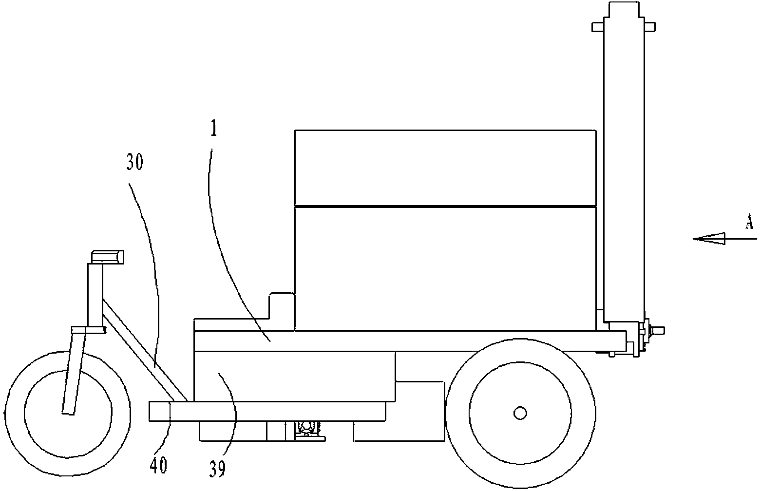
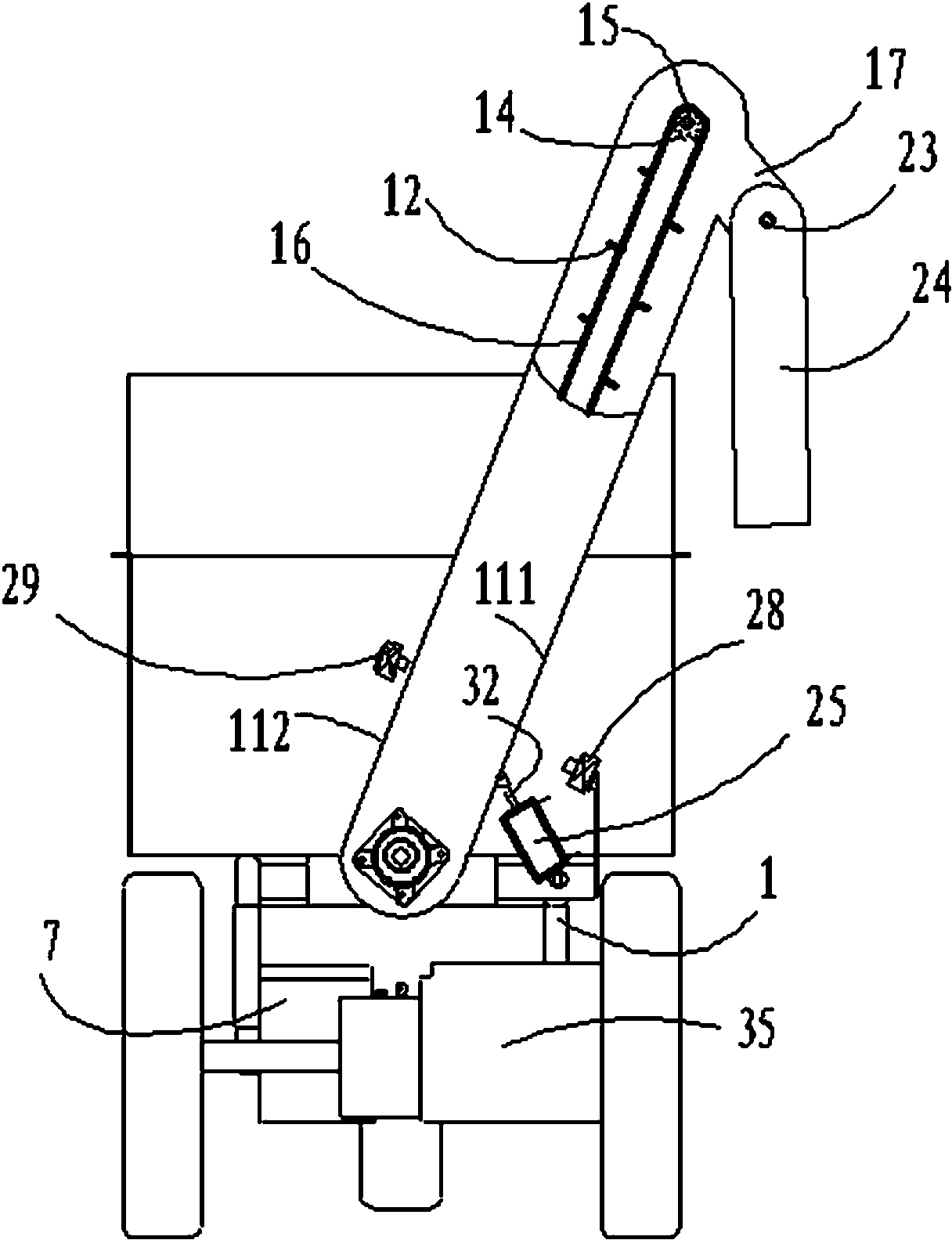
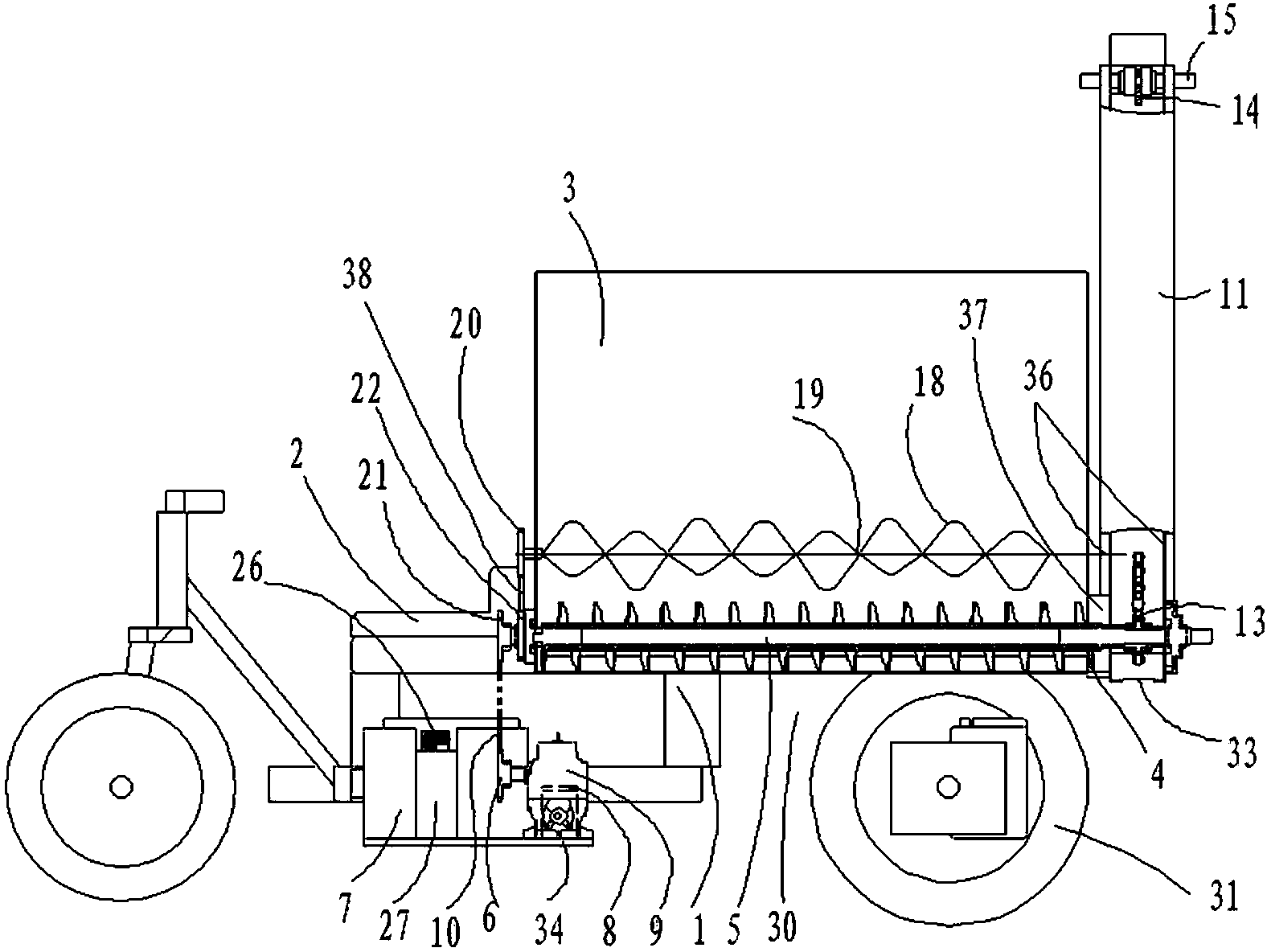
[0025] Such as figure 1 As shown, a feed feeding cart includes a frame 1, a seat 2 is arranged in the front of the frame, a walking motor is arranged under the seat 2, and the walking motor is connected to a DC power supply 7, and the frame at the rear of the seat 2 is provided with A hollow box 3 with an upper opening. The rear end of the box 3 is provided with a box discharge port 4. The lower part of the inner cavity of the box 3 is provided with a conveying auger shaft 5 along the front and rear direction of the car. The front end of the auger shaft 5 extends Outside the front wall of the box body, the rear end of the auger shaft extends from the discharge port 4 of the box body to the rear wall of the box body. The front end of the auger shaft 5 is supported on the frame 1 through the front bearin...


PUM


Abstract

The invention discloses a feed feeding vehicle which comprises a vehicle frame, wherein a seat is arranged at the front part of the vehicle frame; a walking motor is arranged at the lower part of the seat; the walking motor is connected with a direct current supply; a box body is arranged on the vehicle frame at the back part of the seat; a discharge outlet of the box body is formed in the back end of the box body; a transporting auger shaft is arranged at the lower part of the inner chamber of the box body; the front end of the auger shaft extends out of the front wall of the box body; the back end of the auger shaft extends out of the back wall of the box body from the discharge outlet of the box body; the front end of the auger shaft is supported on the vehicle frame; an auger driving direct current motor is arranged on a chassis of the vehicle frame below the seat, is in electric connection with the direct current supply, and transmits power to the auger shaft; a discharging device is arranged on the auger shaft at the back end of the box body; a feed inlet of a discharging pipe is formed in the lower end of the discharging pipe of the discharging device and near one side of the back wall of the box body; the feed inlet of the discharging pipe is connected with the discharge outlet of the box body; a discharge outlet of the discharging pipe is formed in the upper end of the discharging pipe; a feed lifting transportation mechanism is arranged in the discharging pipe. The feed feeding vehicle is particularly suitable for transporting feed, with relatively small space, of small-scale feeding farms.

Description

Technical field [0001] The invention relates to the technical field of feed machinery and equipment, in particular to a feed feeding vehicle. Background technique [0002] The prior art feed feeding vehicles are generally large-tonnage transport vehicles, which are mainly used for the transportation of feed from the outside to the farm by large and medium-sized breeding enterprises. However, they are not suitable for large tonnage, large space occupation, and inflexible transfer. Feed transfer in relatively small spaces within small and medium-sized aquaculture enterprises still requires manual feed transfer in the field. The problem is that the structure is compact, the transfer staff is labor-intensive, and the efficiency is low, and it is easy to cause feed pollution. There is no small integrated transportation and unloading tool suitable for feed transfer within aquaculture enterprises in the prior art. Summary of the invention [0003] The purpose of the present invention is...

Claims


Application Information

Patent Timeline
Patent Type & Authority Applications(China)
IPC IPC(8): A01K5/00A01K39/01B62K5/027B62K7/00B62M7/06
Inventor 鞠恒峰张进李会荣孙家林站余铭张玮
Owner JINAN JINGYIDA AGRI & ANIMAL HUSBANDRY MACHINERY
Learn More