
A diode bending die

A diode and bending technology, which is applied in the field of diode bending molds, can solve problems such as time-consuming, labor-intensive, and difficult problems, and achieve the effects of reducing danger, reducing work difficulty, and ensuring stability

Active Publication Date: 2016-01-13
昌辉精密模具(黄山)有限公司
View PDF5 Cites 0 Cited by
  • Summary
  • Abstract
  • Description
  • Claims
  • Application Information

AI Technical Summary

Problems solved by technology

[0003] In order to overcome the time-consuming and labor-intensive problem of using manual bending in the existing workshops, the invention provides a diode bending mold for switches. The lower mold of the fixture bends diodes, the upper mold is cut by punching and cutting, and the lower mold is taken by sliders. The push rod pushes the material, which can avoid the difficulty of retrieving the material

Method used


Image

  • A diode bending die
  • A diode bending die
  • A diode bending die

Examples


Embodiment Construction

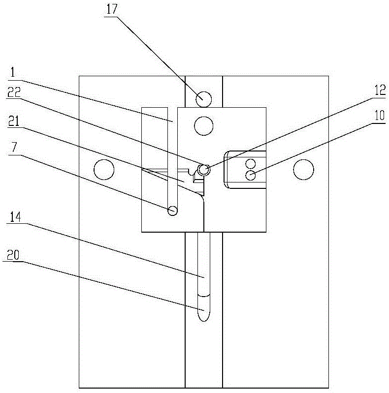
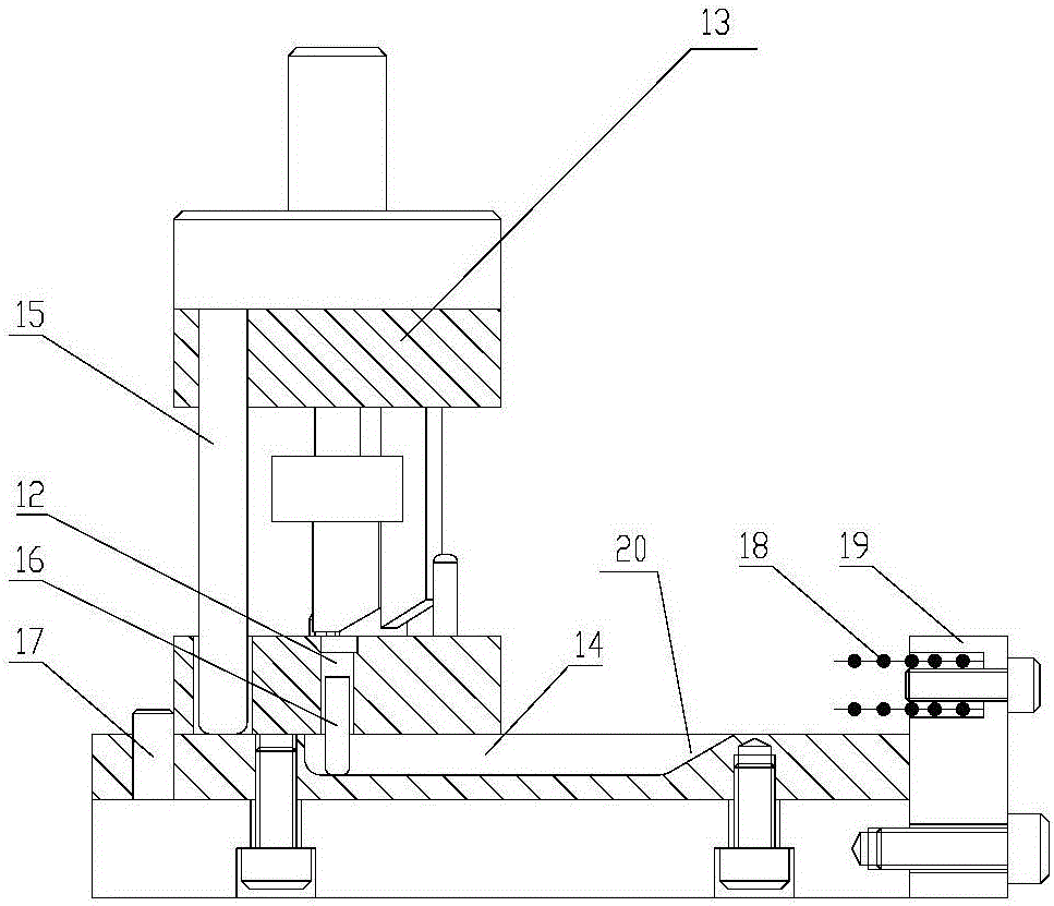
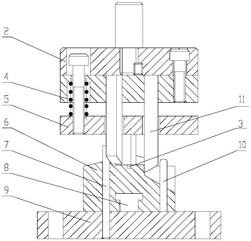
[0019] A diode bending mold, comprising a lower mold 6 and a bottom plate 9; a slide rail 8 and a guide post 7 are installed on the bottom plate 9, and the guide post 7 is fixedly arranged on one side of the slide rail 8; The other side of 8 is also provided with a limit column 10, and the lower mold 6 is slidingly matched with the slide rail 8; A positioning hole 12 for positioning the diode is arranged between the track groove 1 and the track groove 1 . The limiting posts 10 are two upright posts with a distance equal to the thickness of the anode or cathode of a diode.

[0020] After the diode is bent, it is convenient to pick up the parts. The slide rail 8 is provided with a U-shaped groove 14 that matches the positioning hole 12, and a movable push pin 16 is arranged in the positioning hole 12. One section is in the U-shaped groove 14 ; one end of the U-shaped groove 14 is provided with an axial slope 20 of the U-shaped groove.

[0021] Further, after the lower mold sli...


PUM


Abstract

A diode bending mold comprises a base plate, wherein a slide track is mounted on the base plate; a lower mold which can slide along the slide track is mounted on the slide track; a limit post which clamps one pin of a diode is arranged on the lower mold; a guide post which blocks the other pin of the diode is arranged on the base plate; a track groove matched with the guide post is formed in the lower mold; and a positioning hole for positioning the diode is formed in the lower mold. An upper mold matched with the lower mold for cutting the diode is further adopted and adopts an integral structure. The working difficulty and the dangerousness are reduced during piece placing and taking. The diode bending mold adopts a positioning and discharging combined manner, so that the diode bending and cutting stability and taking and placing of the diode are guaranteed; and the diode bending mold is simple in structure, the piece is convenient to take, and the safety coefficient is high.

Description

technical field [0001] The invention relates to a bending die, in particular to a diode bending die, and the die also has a cutting function. Background technique [0002] Crystal diodes and light diodes need to be bent and cut at the two poles of the diodes when they are installed and used. But at present, the diode bending work in the workshop is manually bent and cut. Especially when bending some products with complex structures, it is time-consuming and labor-intensive. And there are the following problems at the same time: 1. Manual bending, high work intensity and low efficiency; 2. Manual bending and cutting are of different lengths, which affect the welding quality of products. Contents of the invention [0003] In order to overcome the time-consuming and labor-intensive problem of using manual bending in the existing workshops, the invention provides a diode bending mold for switches. The lower mold of the fixture bends diodes, the upper mold is cut by punching ...

Claims


Application Information

Patent Timeline
Patent Type & Authority Patents(China)
IPC IPC(8): B21F1/00B21F11/00
Inventor 王进丁王正成朱排进李宏志
Owner 昌辉精密模具(黄山)有限公司
Learn More