Hook arm of buffer load-shedding arresting hook

A technology of arresting hooks and hook arms, which is applied in the direction of lightning arrester hooks, fluid pressure actuating devices, launching/dragging transmissions, etc., can solve the problems of reducing aircraft combat performance, not having the function of buffering and reducing load, and increasing structural weight, etc., to achieve The effect of simple structure, stable working performance and easy implementation

Active Publication Date: 2014-03-19
JIANGXI HONGDU AVIATION IND GRP
View PDF6 Cites 9 Cited by
  • Summary
  • Abstract
  • Description
  • Claims
  • Application Information

AI Technical Summary

Problems solved by technology

The traditional arresting hook arm is a simple rigid structure, figure 1 The structure of the hook arm of the arresting hook in the traditional technology is shown. In the figure, 14 is the connection between the front hook arm and the fuselage, 15 is the rear hook arm, the end of the rear hook arm 15 is the hook head 8, and the front hook arm 14 is connected to the rear hook arm. There is a length adjustment thread 16 between the arms. Such a rigid structure does not have the effect of buffering and reducing loads. The loads generated by the landing arrest are all transmitted to the body structure, which requires the body structure and airborne equipment to have a greater ability to resist axial overload. , resulting in an increase in structural weight and an increase in equipment overload resistance, thereby reducing aircraft combat performance

Method used


Image

  • Hook arm of buffer load-shedding arresting hook
  • Hook arm of buffer load-shedding arresting hook

Examples


Embodiment

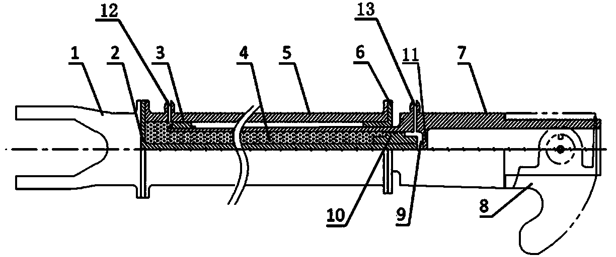
[0015] Example: see figure 2 .

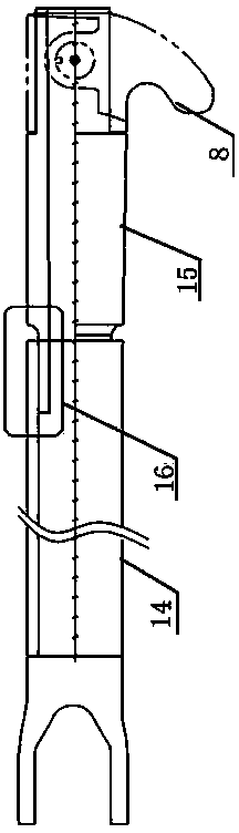
[0016] The invention discloses a buffer and load reduction arresting hook arm, such as figure 2 As shown, one end is a joint 1, and the other end is a hook head 8. Between the joint 1 and the hook head 8, there are an outer cylinder 5 and an inner cylinder 7 in sequence, and the main body of the inner cylinder 7 is large at one end and small at the other. Hollow stepped columnar structure, the main body of the outer cylinder 5 is a hollow columnar structure, the small end of the inner cylinder 7 extends into the outer cylinder 5, and also includes a core rod 2, one end of the core rod 2 is connected to the connector 1 and the outer cylinder 5 The outer end is tightly connected, and the other end extends into the interior of the inner cylinder 7. There is a gap between the outer surface of the small end of the inner cylinder 7 and the inner surface of the outer cylinder 5, and the outer fixed sleeve of the small end of the inner cylinder 7 is...


PUM


Abstract

The invention relates to a hook arm of a buffer load-shedding arresting hook. A connector is arranged at one end of the hook arm, and a hook head is arranged at the other end of the hook arm. An outer cylinder and an inner cylinder are arranged between the connector and the hook head. A main body of the inner cylinder is of a hollow step columnar structure. A main body of the outer cylinder is of a hollow columnar structure. The small end of the inner cylinder extends into the outer cylinder. The hook arm comprises a core rod, wherein one end of the core rod is firmly connected with the outer ends of the connector and the outer cylinder, and the other end of the core rod extends into the inner cylinder; the outer part of the core rod is fixedly sleeved with a second sealing ring which is in interference fit with the inner cylinder; the inner cylinder, the outer cylinder, the core rod, a first sealing ring and the second sealing ring form an oil chamber which is used for accommodating hydraulic oil; a separation plate is arranged inside the large end of the inner cylinder; the separation plate, the inner cylinder, the core rod and the second sealing ring form a buffer cavity; an oil penetration hole is formed in the second sealing ring; the two sealing rings are in sliding fit with the inner walls of the outer cylinder and the inner cylinder respectively; a sliding clearance is formed between the inner end of the outer cylinder and the step of the inner cylinder. The hook arm of the buffer load-shedding arresting hook has the effect of buffering aircraft landing arresting, and is stable in working performance.

Description

technical field [0001] The invention relates to the field of structural design of aircraft auxiliary devices, in particular to a buffer and load reduction arresting hook arm. Background technique [0002] In order to realize the short-distance arrest of carrier-based aircraft, the arresting hook device is usually used to hook the arresting cable when landing, that is, a set of arresting hook device is installed on the fuselage of the aircraft, which is composed of a hook head and a hook arm. on the belly of the fuselage. The traditional arresting hook arm is a simple rigid structure, figure 1 The structure of the hook arm of the arresting hook in the traditional technology is shown. In the figure, 14 is the connection between the front hook arm and the fuselage, 15 is the rear hook arm, the end of the rear hook arm 15 is the hook head 8, and the front hook arm 14 is connected to the rear hook arm. There is a length adjustment thread 16 between the arms. Such a rigid struct...

Claims


Application Information

Patent Timeline
Patent Type & Authority Applications(China)
IPC IPC(8): B64C25/68B64F1/04F15B15/22
Inventor 刘敏辛荣提何明清吴宝林符松海沈亮冷智辉
Owner JIANGXI HONGDU AVIATION IND GRP
Why Eureka
Try Eureka