Multipath partial discharge signal parallel connection method and apparatus

A discharge signal and connection method technology, applied in the direction of testing circuit, testing dielectric strength, etc., can solve the problems of signal failure, manual control, signal loss, etc., achieve low cost, improve equipment operation safety, and avoid loss effects

Active Publication Date: 2014-03-19
STATE GRID CORP OF CHINA +2
View PDF7 Cites 0 Cited by
  • Summary
  • Abstract
  • Description
  • Claims
  • Application Information

AI Technical Summary

Problems solved by technology

That is to say, in the circulator, the signal can only be transmitted in the direction of 1→2, 2→3, 3→4, 4→1, and for the non-selective transmission signal in the multiplex transmission signal, that is, the parallel transmission in the signal bus The signal energy of other signals transmitted by the connecting branch is attenuated by 50%
[0004] In addition, although the general switch can realize the isolation of multiple partial discharge signals to a certain extent, it needs manual control. When the switch is closed, the signal can pass through, and it is bidirectional. When the switch is turned off, the signal cannot pass through.
[0005] Because the switch can not be controlled by the self-triggering closing and closing of the signal in the prior art, so the self-triggering one-way transmission cannot be realized, and the one-way transmission circuit based on the circulator will generate a large number of signals when the signal passes through the signal isolation circuit Energy attenuation, resulting in signal loss

Method used


Image

  • Multipath partial discharge signal parallel connection method and apparatus
  • Multipath partial discharge signal parallel connection method and apparatus
  • Multipath partial discharge signal parallel connection method and apparatus

Examples


Embodiment 1

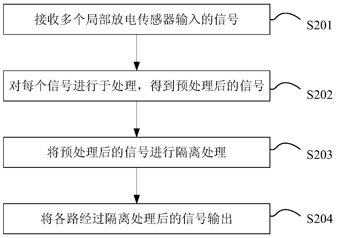
[0047] figure 2 It is a flow chart of a method for parallel connection of multiple partial discharge signals provided by the embodiment of the present application.

[0048] Such as figure 2 As shown, the method includes:

[0049] Step S201: Receive signals input by a plurality of partial discharge sensors.

[0050] Specifically, the partial discharge sensor in this step is a sensor that can generate signals such as UHF signals, ultrasonic signals or high-frequency current signals, so the received signals can be UHF signals, ultrasonic signals or high-frequency current signals Wait for the signal.

[0051] Step S202: Perform preprocessing on each signal to obtain a preprocessed signal.

[0052] In this step, specifically, if the signal is a UHF signal, its preprocessing includes related steps such as amplification, filtering, and detection (that is, down-frequency processing of the UHF signal); when the signal is another type of signal When , the preprocessing of the sig...

Embodiment 2

[0066] On the basis of the first embodiment, the embodiment of the present application also provides a parallel connection device for multiple partial discharge signals, such as Figure 4 As shown, it is a schematic diagram of a parallel connection device for multiple partial discharge signals provided by the embodiment of the present application.

[0067] The unit includes:

[0068] The signal input interface 401 is used for receiving signals input by a plurality of partial discharge sensors.

[0069] Specifically, the partial discharge sensor is a sensor that can generate signals such as ultra-high frequency signals, ultrasonic signals, or high-frequency current signals. Therefore, the received signals can be signals such as ultra-high frequency signals, ultrasonic signals, or high-frequency current signals.

[0070] The signal input interface 401 is a radio frequency signal interface, connected to the partial discharge sensor, and the frequency influence range is 300MHz to...


PUM


Abstract

The invention discloses a multipath partial discharge signal parallel connection method and apparatus. The method comprises: receiving signals inputted by multiple partial discharge sensors, performing preprocessing on the signals, performing isolation processing on the reprocessed signals to enable the signals to be self-triggered and transmitted in one direction, and finally outputting each path of signals after isolation processing. By using the method provided by the invention, multipath signals are isolated and processed so that the signals can be self-triggered, transmitted in one direction and isolated, furthermore, interference-free parallel connection of multipath partial discharge signals can be realized, and the signal loss in a signal transmission process is further avoided. At the same time, the parallel-connected partial discharge signals are all transmitted to a signal bus, and a data acquisition device simultaneously monitors multiple signals so that data acquisition of the same data acquisition device can be realized, and the cost is lowered.

Description

technical field [0001] The present application relates to the technical field of signal control, in particular to a method and device for parallel connection of multiple partial discharge signals. Background technique [0002] In partial discharge signal detection, multiple partial discharge signals are connected in parallel to one transmission bus for transmission. At the interface where any one is merged into the transmission bus, it is necessary to realize the transmission of the merged signal to the transmission bus without loss. The ground isolates the transmission of other signals on the transmission bus to the transmission line. [0003] In the prior art, a circulator is generally used to implement unidirectional signal transmission. Such as figure 1 As shown, the circulator can realize the one-way transmission of the signal, but the isolation of the reverse signal is realized by absorbing the signal energy. That is to say, in the circulator, the signal can only be...

Claims


Application Information

Patent Timeline
Patent Type & Authority Applications(China)
IPC IPC(8): G01R31/14
Inventor 杨雁伏进王谦胡岳李勇汤林逄凯曹灵钰江秀臣
Owner STATE GRID CORP OF CHINA
Why Eureka
Try Eureka