Cell discharge overcurrent protection circuit and cell discharge overcurrent protection method

An overcurrent protection circuit, battery discharge technology, applied in battery circuit devices, emergency protection circuit devices, emergency protection devices with automatic disconnection, etc.

Inactive Publication Date: 2014-03-19
HYTERA COMM CORP
View PDF6 Cites 19 Cited by
  • Summary
  • Abstract
  • Description
  • Claims
  • Application Information

AI Technical Summary

Problems solved by technology

[0004] The technical problem to be solved by the present invention is to provide an overcurrent protection circuit and method for battery discharge, which can well discharge the battery Discharge current is limited within safe limits

Method used


Image

  • Cell discharge overcurrent protection circuit and cell discharge overcurrent protection method
  • Cell discharge overcurrent protection circuit and cell discharge overcurrent protection method
  • Cell discharge overcurrent protection circuit and cell discharge overcurrent protection method

Examples


Embodiment Construction

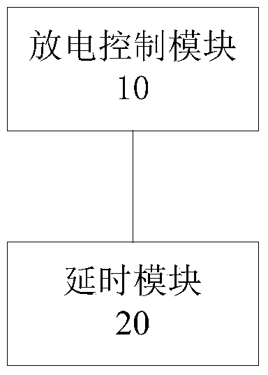
[0031] figure 1It is a logic diagram of Embodiment 1 of the battery discharge overcurrent protection circuit of the present invention. The battery discharge overcurrent protection circuit includes a discharge switch tube (not shown), a discharge control module 10 and a delay module 20, wherein the discharge switch tube Connected in the battery discharge path, the discharge control module 10 is used to detect the discharge current of the battery in real time, and judge whether an overcurrent occurs by comparing the detected discharge current with a preset threshold value, and if no overcurrent occurs, control The discharge switch tube is turned on; if an overcurrent occurs, the discharge switch tube is controlled to be turned off, and when the overcurrent times out, the discharge switch tube is locked in an off state. The delay module 20 is used for judging whether the over-current has timed out by comparing the time when the over-current occurs with the preset delay time.

[...


PUM


Abstract

The invention discloses a cell discharge overcurrent protection circuit and a cell discharge overcurrent protection method. The overcurrent protection circuit comprises a discharge switch tube, a discharge control module used for detecting discharge current of a cell in real time and a time-delay module used for determining whether overcurrent timeout occurs by comparing time of overcurrent generation with the preset time-delay time. Whether overcurrent occurs is determined by comparing the detected discharge current with a preset threshold, if the overcurrent does not occur, the discharge switch tube is controlled to open; if the overcurrent occurs, and the overcurrent timeout occurs, the discharge switch tube is locked in a turn-off state. Through enforcement of the technical scheme, when a load is connected with the cell, the transient current during cell discharge can be reduced, transient energy during cell discharge is effectively restricted, and safety of the cell is improved.

Description

technical field [0001] The invention relates to the field of battery protection, in particular to an overcurrent protection circuit and method for battery discharge. Background technique [0002] For battery-powered electronic equipment, after many battery replacements, most of the contacts of the battery pole pieces turn black, which makes the electronic equipment unreliable when powered on. The main reason is that the discharge current of the battery has not been reasonably controlled. For example, when replacing batteries for electronic equipment, a large pulse current is generated at the moment when the battery pole piece contacts the battery holder of the electronic equipment, and the battery pole piece contact is ignited to generate high temperature oxidation, which causes the battery pole piece contact to blacken. Handheld electronic devices used in some flammable and explosive environments need to limit the energy discharged by the battery within a certain safe valu...

Claims


Application Information

Patent Timeline
Patent Type & Authority Applications(China)
IPC IPC(8): H02J7/00H02H3/087H02H7/18
Inventor 潘启辉卢良飞尤国雄熊运远
Owner HYTERA COMM CORP
Why Eureka
Try Eureka