Molded surface fastener, method for producing molded surface fastener and method for producing cushion body

A manufacturing method and a hook and loop technology, which are applied to fasteners, clothing, applications, etc., can solve problems such as intrusion, increased flow resistance of foamed resin materials, and inability to bend the hook and loop portion 161, achieving high versatility, Easy to manufacture and excellent installation workability

Active Publication Date: 2014-03-19
YKK CORP
View PDF10 Cites 3 Cited by
  • Summary
  • Abstract
  • Description
  • Claims
  • Application Information

AI Technical Summary

Problems solved by technology

[0037] However, in such a molded surface fastener 160 of Patent Document 2, for example, when the foamed resin material has an extremely low viscosity, the foamed resin material is blown from an oblique direction with respect to the molded surface fastener 160, In the case of direct collision with the vertical protective wall portion 163 of the shaped surface fastener 160, even if the flow resistance of the foamed resin material is increased by the vertical protective wall portion 163, there is a possibility that the foamed resin material reaches and enters the engaging element region 165. In the case, there is a possibility that the predetermined desired clamping force cannot be obtained in the clamping element area 165
[0038] In addition, the molded surface fastener 160 of Patent Document 2 is configured to be bendable in the front and back directions and in the width direction as described above by bending the connection portion 162 connecting the surface and back portions 161 . The buckle portion 161 itself is difficult to bend, and each hook and loop portion 161 cannot be properly bent.
[0039] For this reason, in the mold for forming the shock absorber, for example, in the case where the top surface of the convex portion of the shaped surface fastener 160 by suction and fixed is greatly deflected in the front-back direction, although the entire molded surface fastener 160 can be formed along this The ridge portion is curved, but there is a case where a gap is formed between the front and rear end portions of each hook and loop portion 161 and the top surface of the ridge portion.

Method used


Image

  • Molded surface fastener, method for producing molded surface fastener and method for producing cushion body
  • Molded surface fastener, method for producing molded surface fastener and method for producing cushion body
  • Molded surface fastener, method for producing molded surface fastener and method for producing cushion body

Examples


Embodiment 1

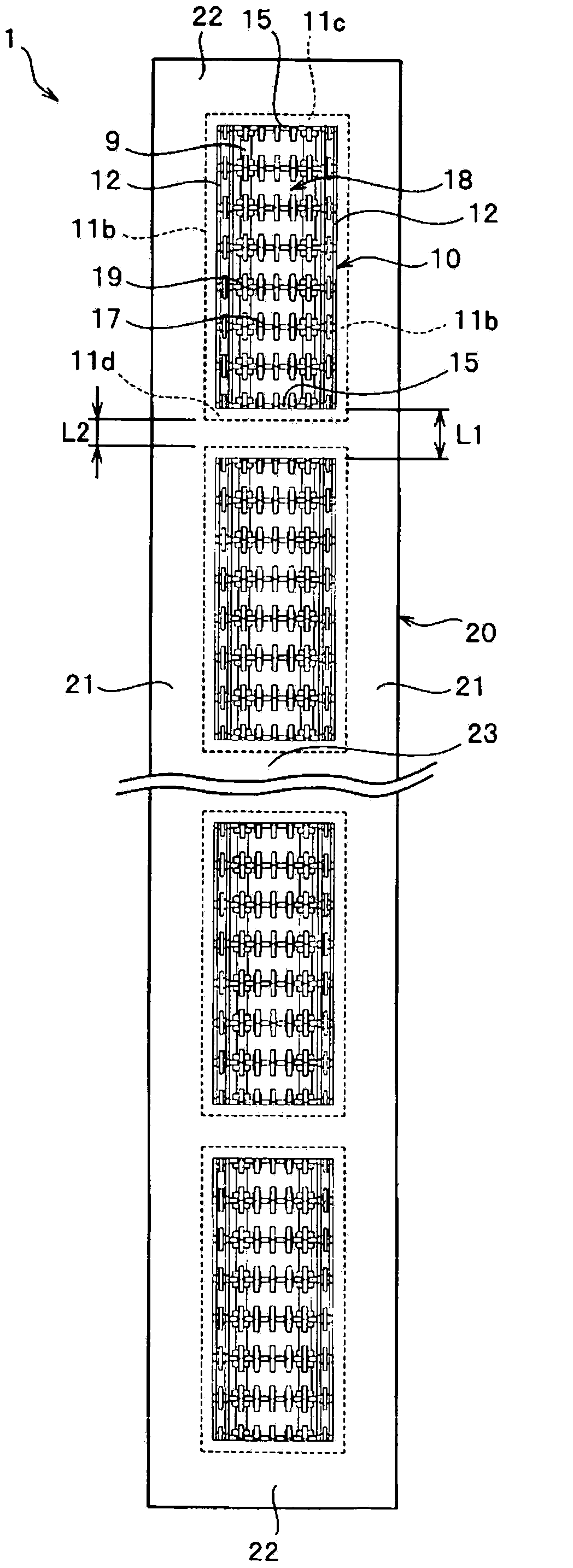
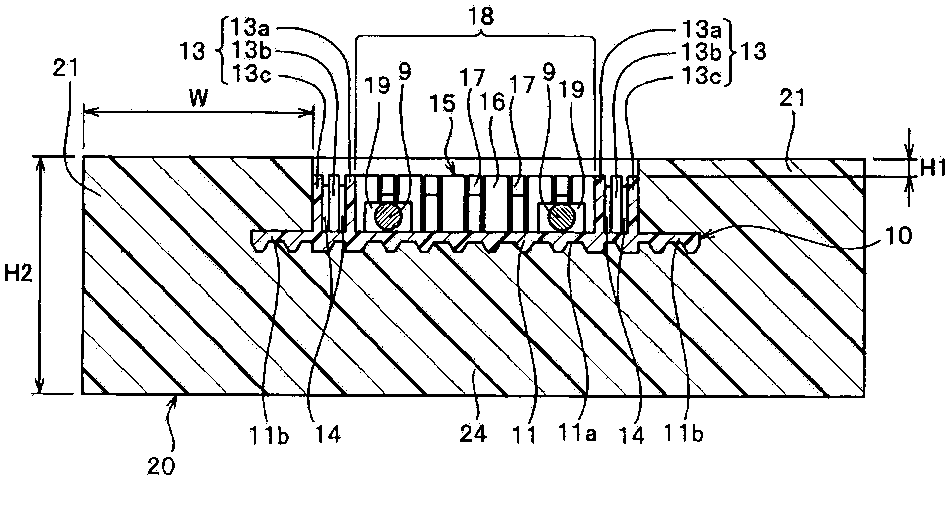
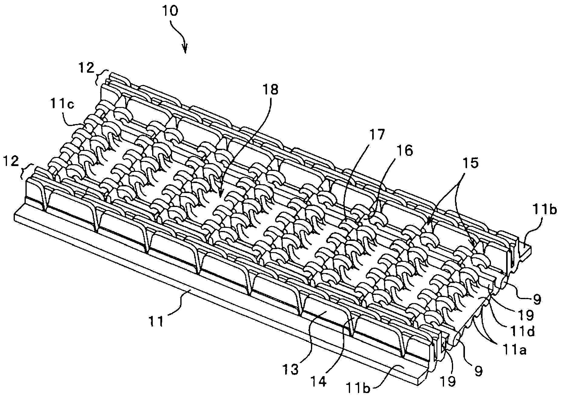
[0142] figure 1 It is a plan view showing the molded surface fastener related to the present embodiment 1, figure 2 is a cross-sectional view of the molded surface fastener. in addition, image 3 It is a perspective view which shows only the surface fastener part which comprises a molded surface fastener.

[0143] In addition, in the description of the lower surface, the longitudinal direction of the base portion of the molded surface fastener is defined as the front-rear direction, and the width direction of the base portion is defined as the left-right direction. In addition, the front-back direction of the base part is defined as the up-down direction, and in particular, the direction on the side where the engaging elements are arranged with respect to the base part is defined as upward, and the direction on the opposite side is defined as downward.

[0144] The molded surface fastener 1 according to the present embodiment 1 has a plurality of surface fastener parts 10...

Embodiment 2

[0290] Figure 29 It is a plan view showing the molded surface fastener related to the present embodiment 2, Figure 30 is a cross-sectional view of the molded surface fastener.

[0291] The molded surface fastener 2 according to the present embodiment 2 has a plurality of surface fastener portions 80 and a connecting member 85 connecting these surface fastener portions 80, and each surface fastener portion 80 has its center position in the width direction aligned along the longitudinal direction. They are arranged on a straight line and connected by a connecting member 85 .

[0292] Each fastening tape portion 80 has a flat base portion 81 , left and right vertical protective wall portions 12 erected on the upper surface of the base material portion 81 , and a plurality of vertical protective wall portions 12 disposed between the left and right vertical protective wall portions 12 . The engaging element (male engaging element) 17, the plurality of lateral protective wall bo...

Embodiment 3

[0314] Figure 33 It is a plan view showing the molded surface fastener related to the present embodiment 3, Figure 34 It is a plan view which shows the surface fastener part which comprises this molded surface fastener.

[0315]The molded surface fastener 3 according to the third embodiment has a plurality of surface fastener portions 100 and a connection member 20 for connecting these surface fastener portions 100 .

[0316] Each fastening tape portion 100 has a flat base portion 101, left and right vertical protective wall portions 12 erected on the upper surface of the base material portion 101, and a plurality of vertical protective wall portions 12 disposed between the left and right vertical protective wall portions 12. The engaging element (male engaging element) 17, the plurality of lateral protective wall bodies 16 constituting the lateral protective wall portion 15 together with the engaging element 17, and the linear liner fixed to the upper surface side of the b...


PUM

PropertyMeasurementUnit
thicknessaaaaaaaaaa

Abstract

This molded surface fastener (1, 1a, 1b, 2, 3, 4, 5, 6, 7) comprises a plurality of surface fastener portions (10, 80, 100, 110) and a coupling member (20, 20a, 85, 115, 125, 135, 145) made of a resilient body that connects the surface fastener portions (10, 80, 100, 110). The coupling member (20, 20a, 85, 115, 125, 135, 145) comprises a pair of lateral wall coupling portions (21, 21a, 86, 116, 126, 136, 146) which is disposed in succession along a longitudinal direction on each side of an engaging element area (18) and which connects the surface fastener portions (10, 80, 100, 110). According to the present invention, when molding and integrating the molded surface fastener (1, 1a, 1b, 2, 3, 4, 5, 6, 7) with the cushion body, penetration of resin materials into the engaging element area (18) of the surface fastener portions (10, 80, 100, 110) is prevented so that a desired fastening strength can be stably ensured at the engaging element area (18).

Description

technical field [0001] The present invention relates to a molded surface fastener that is integrated on the surface of a foam when molding a foam and a method for manufacturing the same, and more particularly relates to a plurality of surface fasteners connected by a connecting member made of an elastic body, and, in A molded surface fastener that prevents intrusion of a foamed resin material into an engaging element forming region of a surface fastener portion during foam molding, and a method for producing the same. Background technique [0002] Seats for automobiles and trains, various sofas, and office seats, etc., are mostly made of fiber fabrics, natural or Constructed of surface materials such as synthetic leather. In order to maintain a sitting posture that is not tiring even when sitting for a long time, cushioning bodies used in such various seats may have a curved surface made of uneven shapes satisfying ergonomics. [0003] Also, when covering the surface of th...

Claims


Application Information

Patent Timeline
Patent Type & Authority Applications(China)
IPC IPC(8): A44B18/00
CPCA44B18/0049A44B18/0015B29C43/222A44B18/0019A44B18/0076Y10T24/2767
Inventor 奥田健司今井进一寺田峰登高田祐治
Owner YKK CORP
Why Eureka
Try Eureka