
Electric dust collector

A vacuum cleaner, electric technology, applied in the direction of vacuum cleaners, suction filters, cleaning equipment, etc., can solve the problems of hair removal troubles, reduced suction power of vacuum cleaners, etc.

Active Publication Date: 2014-03-26
PANASONIC CORP
View PDF4 Cites 5 Cited by
  • Summary
  • Abstract
  • Description
  • Claims
  • Application Information

AI Technical Summary

Problems solved by technology

Therefore, the suction power of the vacuum cleaner is reduced, and it is very troublesome to remove pet hair such as dogs and cats stuck in the through hole.

Method used


Image

  • Electric dust collector
  • Electric dust collector
  • Electric dust collector

Examples


Embodiment approach

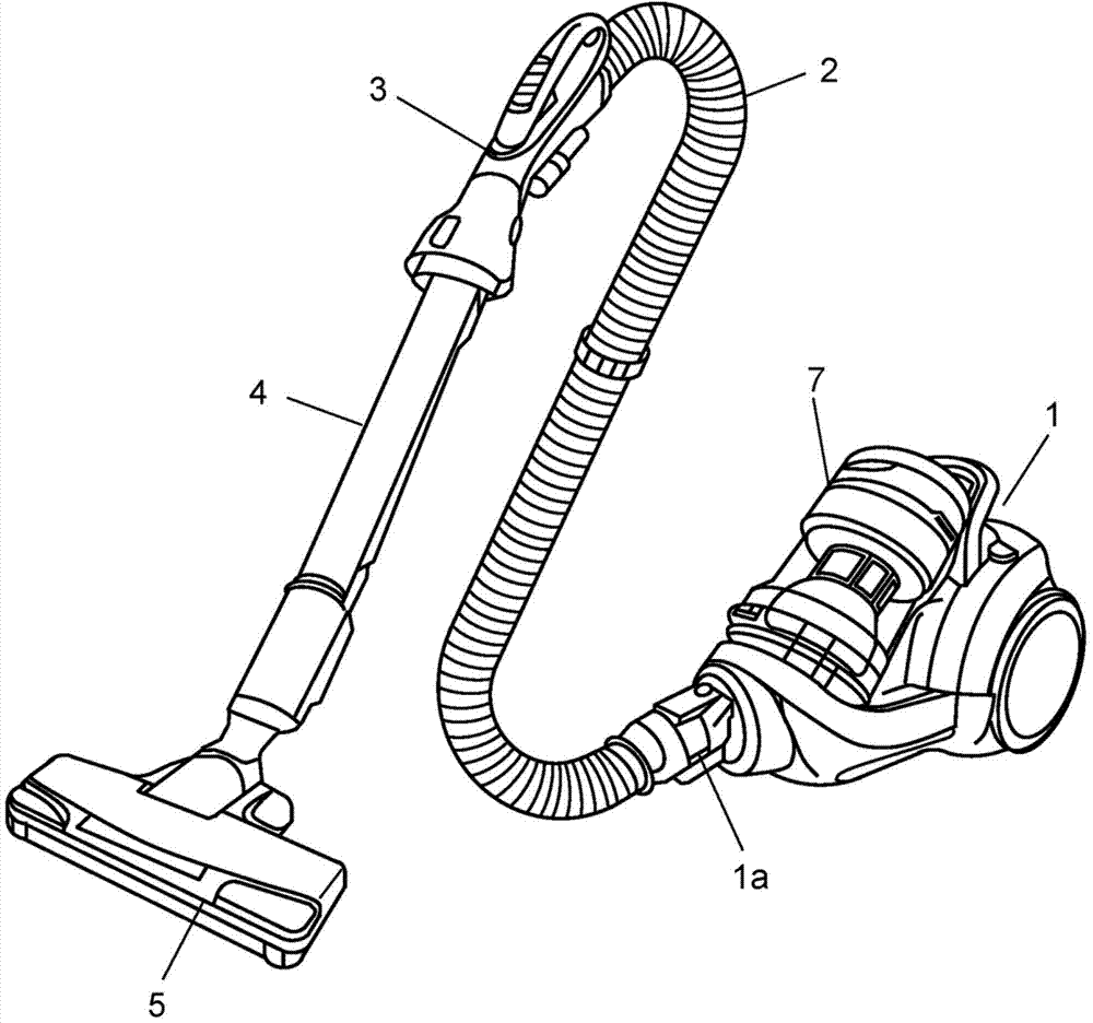
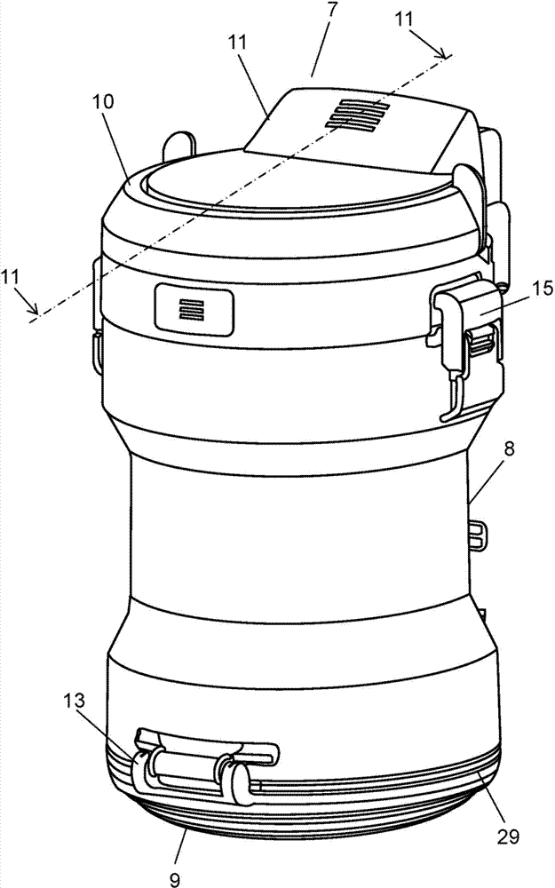
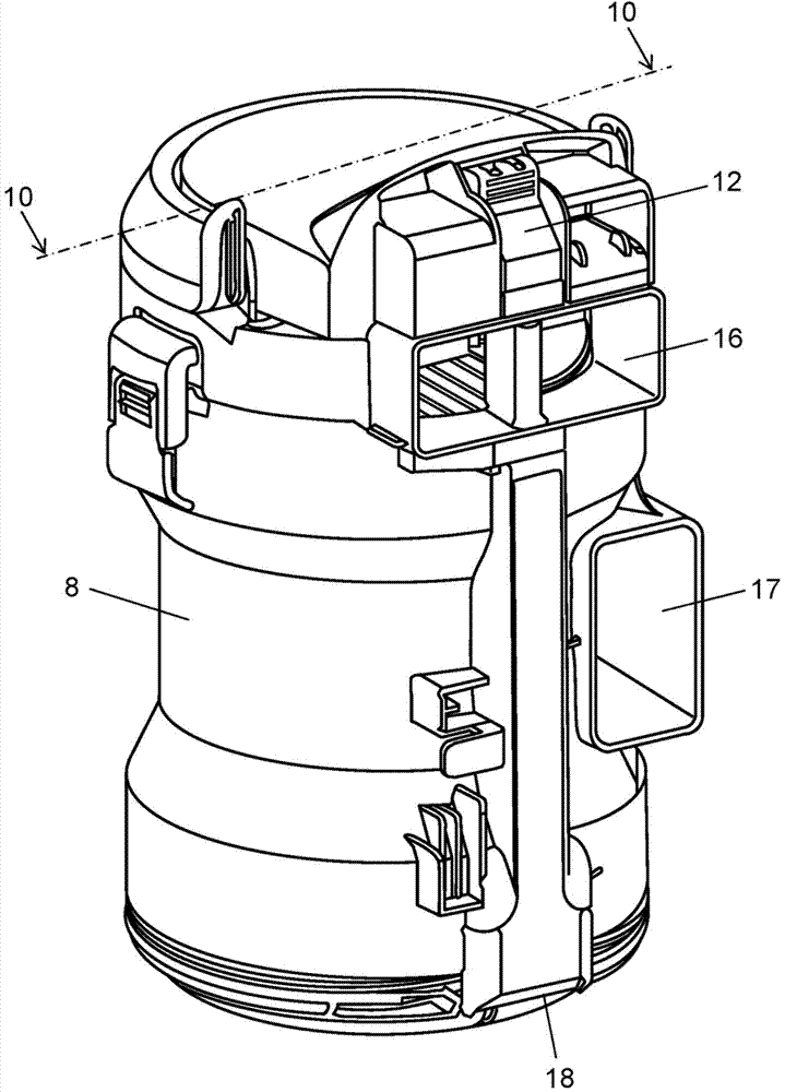
[0025] Below, use Figure 1 to Figure 11 The electric vacuum cleaner provided with the dust collector in embodiment of this invention is demonstrated.

[0026] First, the main use Figure 1 to Figure 3 The appearance structure of the electric vacuum cleaner and dust collector of this embodiment is demonstrated.

[0027] Such as figure 1 As shown, the electric vacuum cleaner equipped with the dust collector of this embodiment is composed of at least a vacuum cleaner main body 1, a hose 2, a connecting pipe 3, an extension pipe 4, a suction member 5, and the like. The hose 2 is connected to the suction port 1a provided in the front part of the cleaner main body 1. As shown in FIG. The connecting pipe 3 is provided at the front end of the hose 2 . The extension pipe 4 is connected with the connecting pipe 3 . The suction tool 5 is provided at the front end of the extension pipe 4 and has an opening (not shown) for sucking dust.

[0028] In addition, an electric blower (not ...


PUM


Abstract

The invention provides an electric dust collector. A dust-collecting device of the electric dust collector comprises a structure configuring a primary filter (21) configured in the following manner: in the primary filter (21) provided with a plurality of through holes penetrating through an upstream side surface and a downstream side surface of the primary filter (21), a direction of a central axis and a forward direction of an outer side swirling airflow (61) flowing on the upstream side surface of the primary filter (21) form a second inclined angle which is downward inclined opposite to the forward direction. The central axis is a straight line of connecting an opening center of a first etching hole and an opening center of a second etching hole. Therefore, a declining swirling airflow (61) going toward a direction of a dust-collecting chamber (33) can be generated in the inner circumference of the primary filter (21), so that the dust can be prevented from flying; and blockage of the filter can be prevented.

Description

technical field [0001] The invention relates to an electric vacuum cleaner, in particular to a dust collecting device of the electric vacuum cleaner. Background technique [0002] The dust collector of the recent cyclone cleaner has the structure disclosed, for example in Japanese Patent No. 4430118 (hereinafter referred to as "Patent Document 1"). [0003] The dust collecting device of the vacuum cleaner described in Patent Document 1 swirls the air sucked together with the dust from the suction piece in the cylindrical dust collecting part, and separates the dust mixed in the air by centrifugal force. Collect the separated coarse dust into the dust collection chamber under the cylindrical dust collection part. The fine dust after passing through the primary filter is collected by the secondary filter provided on the periphery of the primary filter, and the primary filter is formed by forming a plurality of minute through holes in a metal plate. In addition, the dust coll...

Claims


Application Information

Patent Timeline
IPC IPC(8): A47L5/12A47L9/10
Inventor 仲本博司吉川达夫伊藤健二
Owner PANASONIC CORP
Learn More