
Peripheral transmission sludge suction method and suction dredge adopting gas stripping device

A technology of peripheral transmission and sludge suction machine, which is applied in the direction of the feeding/discharging device of the settling tank, etc., can solve the problems of large amount of sludge accumulated in the secondary sedimentation tank and weak mud suction ability, and achieve simple equipment structure and power equipment. Effect of less and enhanced sludge suction capacity

Inactive Publication Date: 2014-03-26
CEEP CO LTD
View PDF5 Cites 15 Cited by
  • Summary
  • Abstract
  • Description
  • Claims
  • Application Information

AI Technical Summary

Problems solved by technology

[0006] The purpose of the present invention is to propose a new type of peripheral transmission mud suction machine in view of the defects of the existing peripheral transmission mud suction machine that have weak mud suction ability, large amount of sludge accumulated in the secondary sedimentation tank or no treatment means for deactivated sludge. , especially equipped with the peripheral transmission sludge suction machine of the air lift device, forming a new type of equipment, which greatly improves the sludge lifting and suction capacity and can meet the use requirements under various working conditions

Method used


Image

  • Peripheral transmission sludge suction method and suction dredge adopting gas stripping device
  • Peripheral transmission sludge suction method and suction dredge adopting gas stripping device
  • Peripheral transmission sludge suction method and suction dredge adopting gas stripping device

Examples


Embodiment Construction

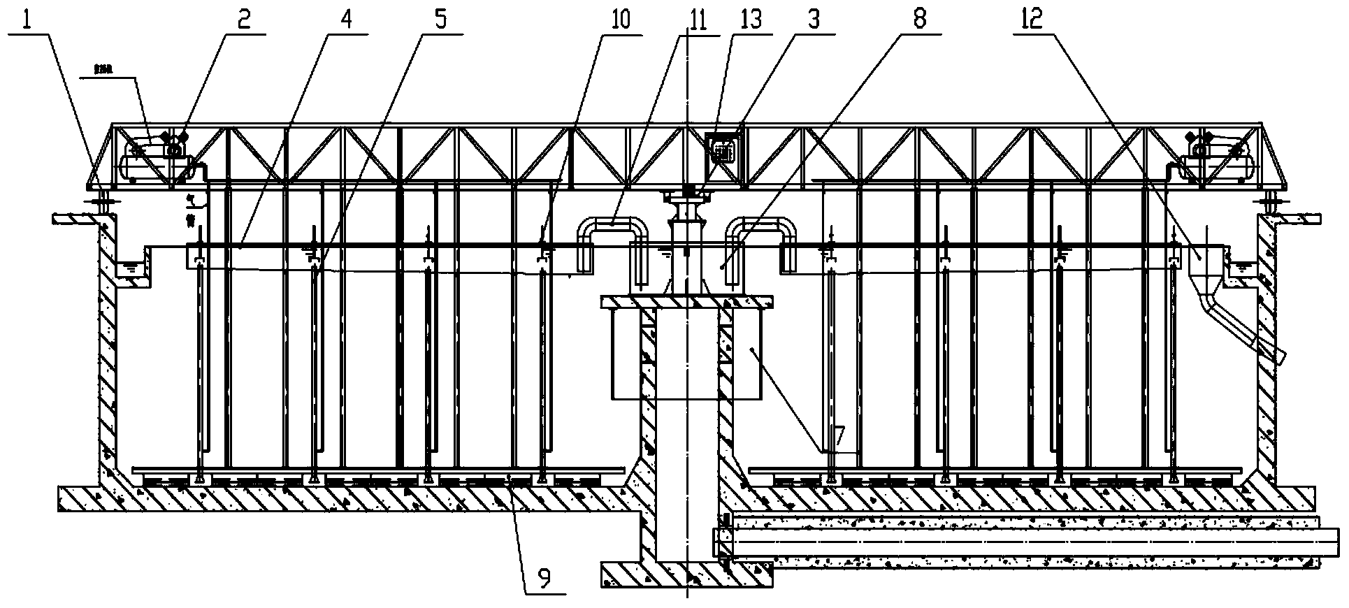
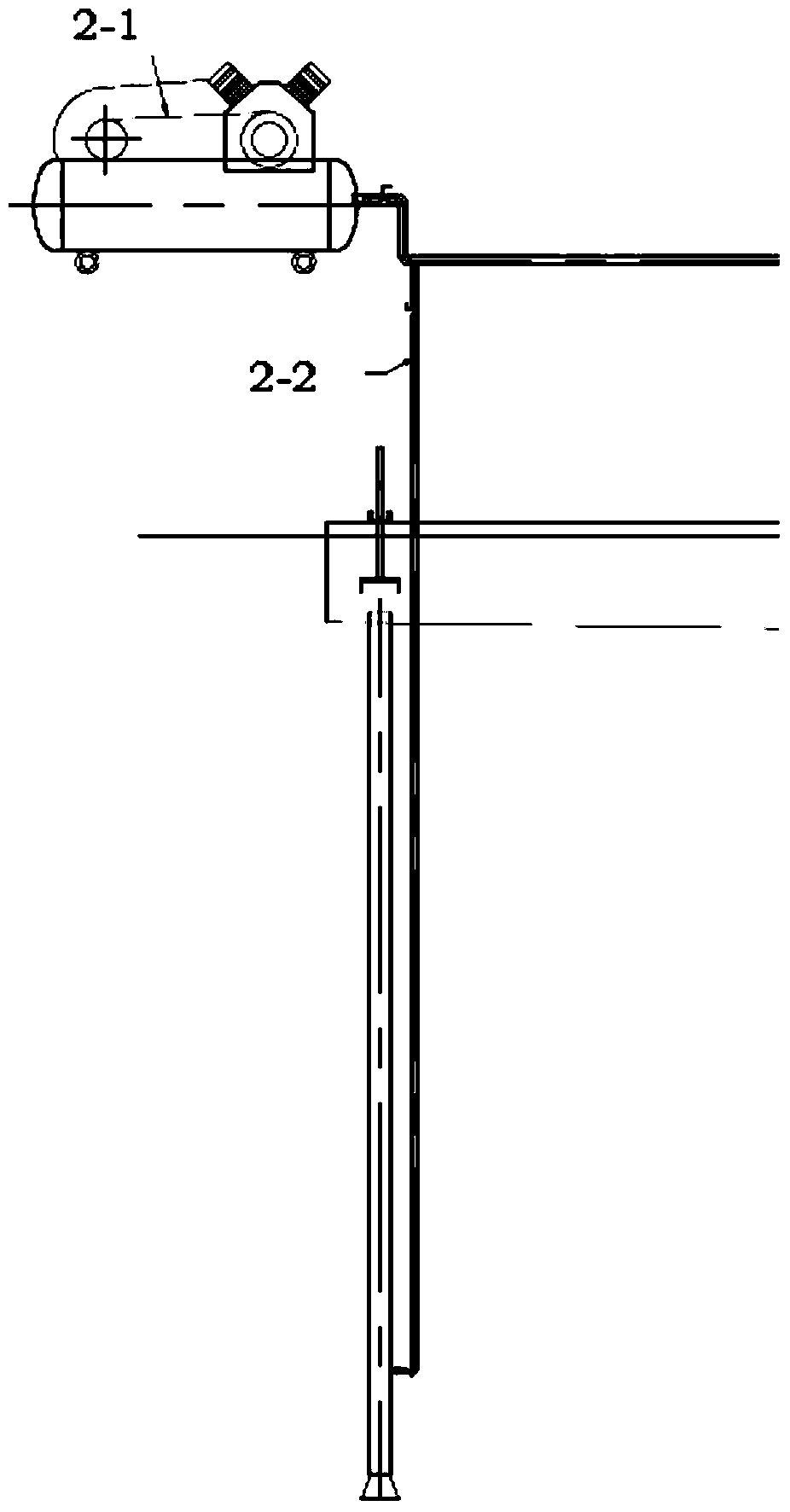
[0023] Equipped with an air lift device, the peripheral transmission mud suction machine adopts the peripheral drive device (1), adopts the central fixed shaft (3) and rotates in a circle with (3) as the center of the circle; the sludge enters from the bottom pipe of the sedimentation mud, and is passed through the central steady flow cylinder (7), evenly enters the sedimentation tank, and the central steady flow cylinder (7) plays the role of stabilizing and buffering, avoiding the agitation in the tank caused by the impact of the incoming water flow, so that maintaining a stable water flow is conducive to the sedimentation of the tank body sludge; equipped with air compression System (2), suction pipe (5), mud collection tank (6), mud scraper (9), and the sludge collected by the mud scraper (9) is concentrated into the mud collection tank by the suction pipe (5) through rotation In (6), the suction pipe is equipped with an air inlet pipe. When the amount of sludge is light, t...


PUM


Abstract

The invention discloses a peripheral transmission suction dredge adopting a gas stripping device. The suction dredge comprises a peripheral driving device, a central fixed shaft, a central steady flow drum, an air compressor unit, a gas distribution pipeline, sludge suction pipes, a sludge collecting tank, a scraper, siphons, a central sludge collecting drum and a main service bridge, wherein the peripheral driving device (1) is mounted at the upper part of the sludge collecting tank and positioned on the main service bridge, and circumferentially rotates by taking the central fixed shaft (3) as the circle center; the central sludge collecting drum is positioned in the center of the sludge collecting tank, and the central steady flow drum (7) is arranged at the lower part of the central sludge collecting drum; the scraper (9) rotates gathered sludge to enable the sludge to be collected in the sludge collecting tank (6) via the sludge suction pipe (5); the sludge suction pipes are provided with the air compressor unit (2) and a gas inlet pipe communicated with the gas distribution pipeline, and adjustable cover caps are arranged on sludge outlets in the upper parts of the sludge suction pipes (5). The peripheral transmission suction dredge has the advantages that the requirements for removal of high concentration and high density sludge can be satisfied, and the processing capability of the equipment is improved; the equipment is simple in structure, and the investment cost of construction is low; the equipment is only equipped with a small power crane motor and the air compressor, so that the less energy consumption is realized, and the running cost is low; the suction dredge is high in running reliability, and can run continuously for 24 hours.

Description

technical field [0001] The invention is an environment-friendly method and equipment, especially a transmission mud suction method and equipment equipped with an air lifting device. Background technique [0002] According to the position in the sewage treatment process, the sedimentation tank can be divided into two types: the primary sedimentation tank and the secondary sedimentation tank. The primary sedimentation tank is generally set after the grit chamber of the sewage treatment plant and before the aeration tank, and the secondary sedimentation tank is set after the aeration tank and before advanced treatment or discharge. The secondary settling tank is an important part of the activated sludge system. Its main function is to separate the sludge, clarify the mixed solution, concentrate and return the activated sludge. After the sewage is biologically treated, it must enter the secondary settling tank for mud-water separation, and the clarified treated water can only b...

Claims


Application Information

Patent Timeline
Patent Type & Authority Applications(China)
IPC IPC(8): B01D21/24
Inventor 徐元宝王祥张平王旭岳伟
Owner CEEP CO LTD
Learn More