

Workpiece orienting device with sliding hook
A technology of orientation device and sliding hook, which is applied in the direction of conveyor objects, transportation and packaging, etc., can solve the problems of inability to realize workpieces, low performance, etc., and achieve the effect of high work efficiency.
- Summary
- Abstract
- Description
- Claims
- Application Information
AI Technical Summary
Problems solved by technology
Method used
Image

Examples
Embodiment Construction
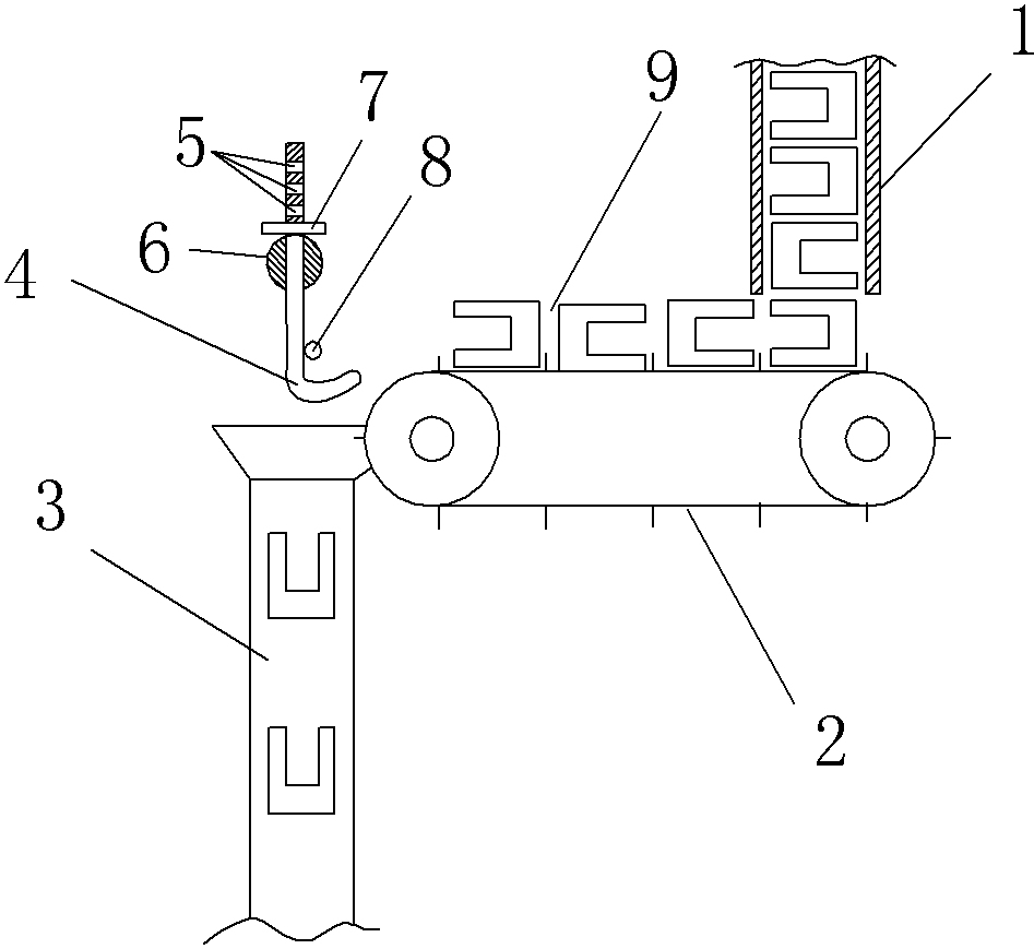
[0008] The reference numerals in the accompanying drawings of the specification include: feed pipe 1 , conveyor belt 2 , orientation channel 3 , slide hook 4 , pin hole 5 , rotating shaft 6 , pin 7 , front stop pin 8 , and workpiece 9 .
[0009] Below in conjunction with accompanying drawing and embodiment the technical solution of the present invention is further described:
[0010] Such as figure 1 As shown, the present invention provides a kind of orienting device with sliding hook, comprises frame, frame top continuous feeding workpiece 9 feeding pipe 1, the conveyer belt 2 that can convey workpiece 9 on the frame and orientation channel 3, described feeding The discharge port of the inlet pipe 1 is close to the input end of the conveyor belt 2, and the directional channel 3 is arranged on the output end of the conveyor belt 2. A plurality of partitions can be arranged at equal intervals on the conveyor belt, and adjacent partitions form a feed trough. The top of the dire...
PUM
 Abstract
Description
Claims
Application Information