Vibratory feeder of bearing retainer

A technology of bearing cage and vibration feeding, which is applied in the direction of conveyor objects, transportation and packaging, etc., can solve the problems of easy fatigue of operators, inconsistent direction of cage, low work efficiency, etc.

Active Publication Date: 2014-03-26
斯凯孚(新昌)轴承与精密技术有限公司
View PDF8 Cites 14 Cited by
  • Summary
  • Abstract
  • Description
  • Claims
  • Application Information

AI Technical Summary

Problems solved by technology

Its shortcoming is that the cage must be inserted and sleeved on the rod in the same direction to be used, which requires the staff to pay great attention to the direction of the cage and not to insert it backwards, so that the work efficiency is very low, and the operator is also very easy to feel fatigue
If we use the existing vibrating feeder to load the cage, there will be problems in the cages coming out of the outlet of the vibrating feeder that some cages face upward in direction A and some face upward in direction B. , that is to say, the direction of the cages coming out is not uniform, so that the cages coming out of the existing vibrating feeder cannot be used for bearing industrial assembly

Method used


Image

  • Vibratory feeder of bearing retainer
  • Vibratory feeder of bearing retainer
  • Vibratory feeder of bearing retainer

Examples


Embodiment Construction

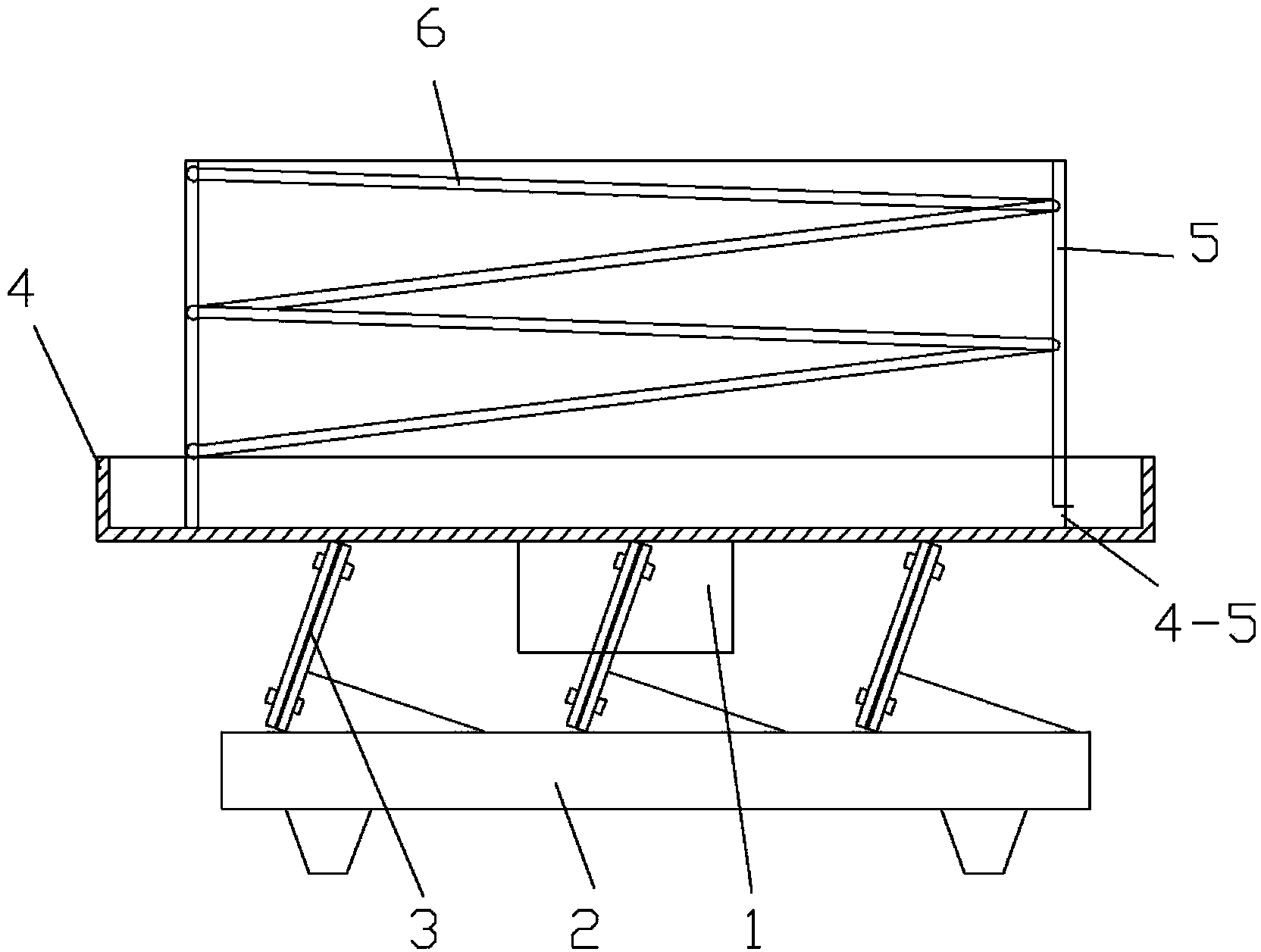
[0022] Example: see Figures 3 to 7 As shown, the bearing cage vibrating feeder includes a vibrating motor 1, a base 2 and a reed 3, the vibrating motor 1 is fixed on the lower part of the vibrating feeding tray 4, and the upper end of the reed 2 is fixed on the upper and lower ends of the vibrating feeding tray 4 Fixed on the base 2, the four reeds 2 are distributed in the lower part of the vibrating feeding tray 4 in a circular array centered on the center of the vibrating feeding tray 4, and the reeds 2 form an angle of 30-60 degrees with the horizontal plane;

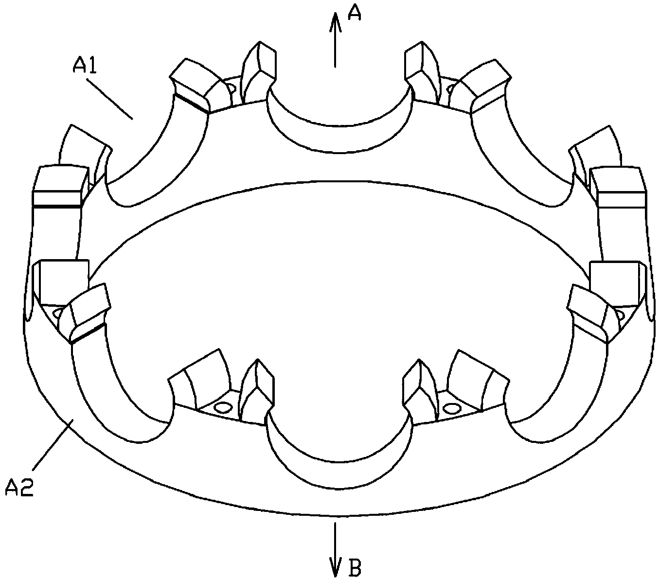
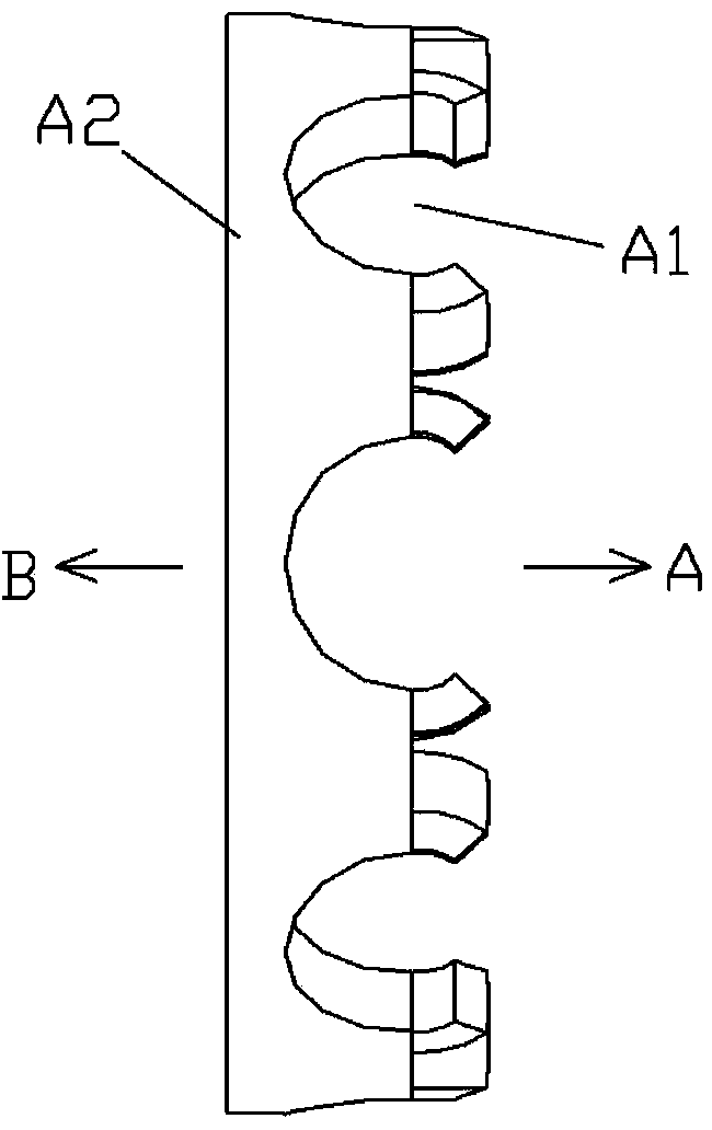
[0023] A feeding cylinder 5 is welded and fixed on the vibrating feeding tray 4, and a spirally rising feeding piece 6 is welded and fixed on the inner wall of the feeding cylinder 5, and the first conveying channel 7 and the second conveying channel 8 are fixed on the feeding cylinder. 5, the outlet of the first conveying channel 7 faces the inlet of the second conveying channel 8, and the first conveying channel b...


PUM


Abstract

Disclosed is a vibratory feeder of a bearing retainer. The upper ends of leaf springs are fixed to a vibratory material receiving disc, and the lower ends of the leaf springs are fixed to a base. The four leaf springs are distributed at the lower portion of the vibratory material receiving disc in an annular-array mode by using the center of the vibratory material receiving disc as the center. The included angle formed between the leaf springs and the horizontal plane is 30-60 degrees. A feeding cylinder is fixedly welded to the vibratory material receiving disc. A spiral-escalation feeding piece is fixedly welded to the inner wall of the feeding cylinder. A first material conveying channel and a second material conveying channel are fixed to the feeding cylinder. A discharging outlet of the first material conveying channel faces a feeding inlet of the second material conveying channel. The distance between a first material conveying channel base plate of the first material conveying channel and the ground is larger than that between a second material conveying channel base plate of the second material conveying channel and the ground. A turnover rod is fixed to the first material conveying channel base plate and located at the position of the discharging outlet of the first material conveying channel. According to the vibratory feeder of the bearing retainer, it can be ensured that the face of the discharged bearing retainer in the direction A is arranged downwards.

Description

Technical field: [0001] The invention relates to the technical field of bearing production, in particular to a vibration feeder for a bearing cage. Background technique: [0002] At present, the cage loading on the bearing assembly production line uses a rod-type feeder, and then the bearing cage is manually inserted on the rod of the rod-type feeder, and then the rod-type feeder is installed on the bearing. assembly line. Its shortcoming is that the cage must be inserted and sleeved on the rod in the same direction to be used, which requires the staff to pay great attention to the direction of the cage and not to insert it backwards, so that the work efficiency is very low, and the operator is also very easy to feel fatigue. In order to continuously use the vibrating feeder to feed the bearing assembly line, it is necessary to make the direction of the cage coming out of the vibrating feeder discharge channel uniform, so that the continuous cage feeding device can be desi...

Claims


Application Information

Patent Timeline
IPC IPC(8): B65G47/256
Inventor 盛戬戬胡贤林俞锦松张小明
Owner 斯凯孚(新昌)轴承与精密技术有限公司
Why Eureka
Try Eureka