Processing apparatus and method of processing and method of making leaf spring

a processing apparatus and leaf spring technology, applied in the direction of lasers, head supports, manufacturing tools, etc., can solve the problem of not being able to stabilize the driving voltage immediately after, and achieve the effect of high accuracy

Inactive Publication Date: 2009-04-23
FUJITSU LTD
View PDF7 Cites 67 Cited by
  • Summary
  • Abstract
  • Description
  • Claims
  • Application Information

AI Technical Summary

Benefits of technology

[0017]The method allows formation of a beam spot of the laser beam on the surface of the leaf spring. The energy of the beam spot enables bending of the leaf spring, namely the establishment of a gorge. Moreover, the optical system serves to adjust the energy of the laser beam irradiated to the leaf spring. The energy of the laser beam instantly changes as compared with the case where the energy of the laser beam is adjusted based on a driving voltage applied to a laser oscillator, for example. The leaf spring is thus processed by using the laser beam with high accuracy.

Problems solved by technology

It is impossible to stabilize the driving voltage immediately after the driving voltage changes.

Method used


Image

  • Processing apparatus and method of processing and method of making leaf spring
  • Processing apparatus and method of processing and method of making leaf spring
  • Processing apparatus and method of processing and method of making leaf spring

Examples


first embodiment

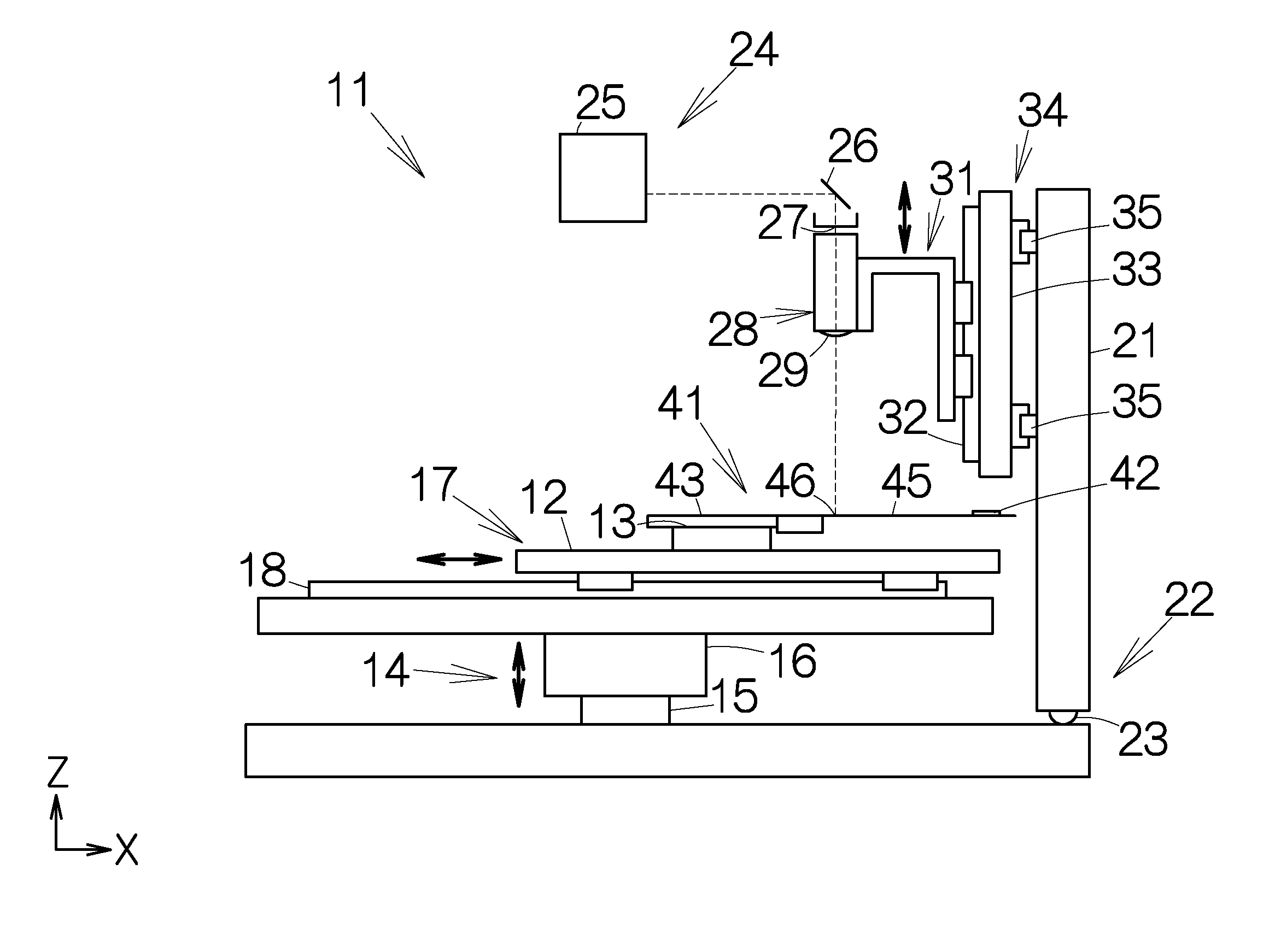
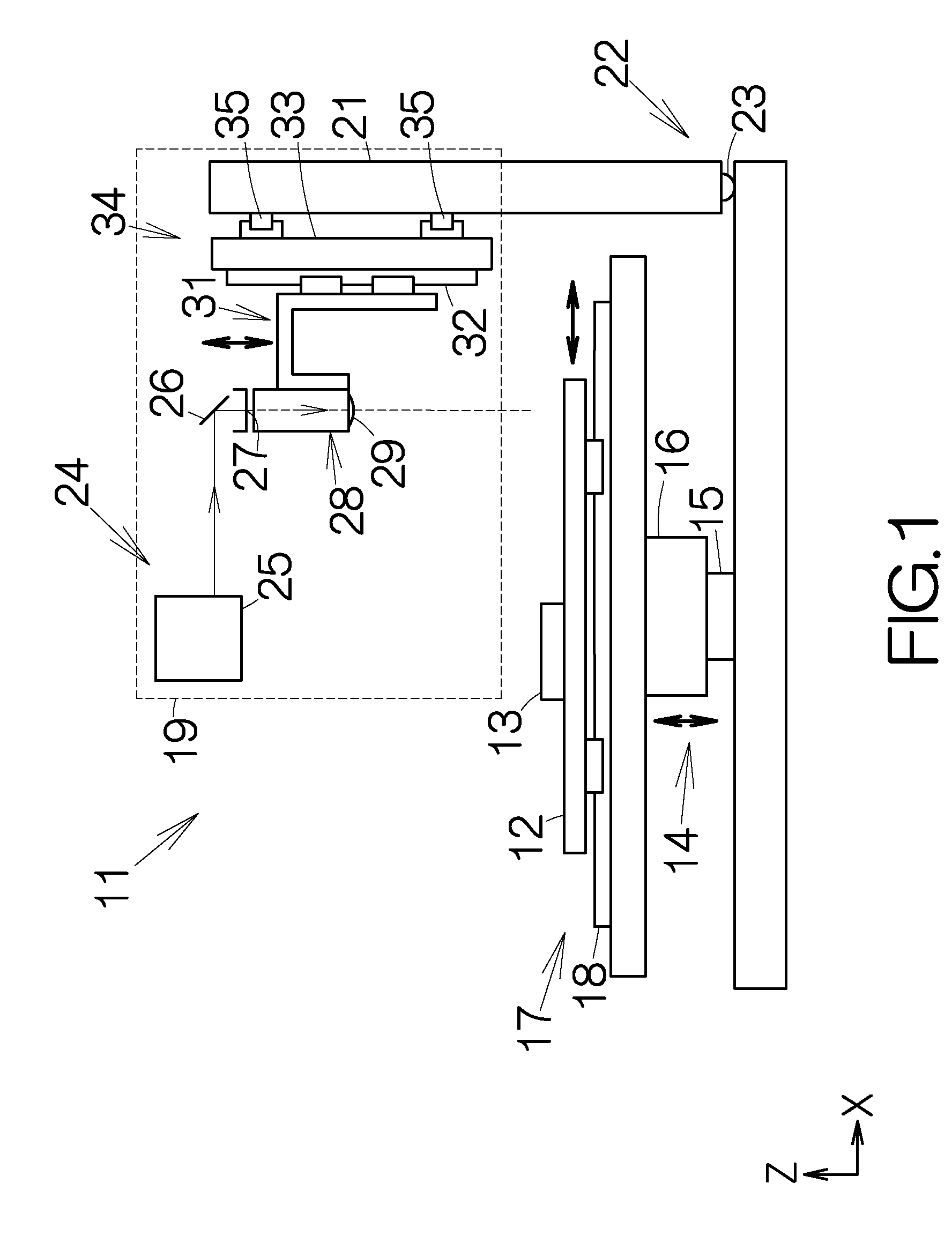
[0036]An optical system 28 is connected to the output end 27 of the laser source 24. The optical system 28 includes a collective lens 29. The optical axis of the collective lens 29 is aligned with the optical axis of the aforementioned output end 27. The collective lens 29 is designed to focus the laser beam. The laser beam is emitted in the direction of gravity through the collective lens 29. The position of the collective lens 29 can be changed in the z-axis direction. The collective lens 29 is attached to a z-axis positioning mechanism 31. The z-axis positioning mechanism 31 drives the collective lens 29 in the z-axis direction. The z-axis positioning mechanism 31 includes a guide rail 32. The collective lens 29 is mounted on the guide rail 32. The guide rail 32 extends on a support member 33 in the vertical direction or in the z-axis direction. The guide rail 32 is designed to guide the movement of the collective lens 29 in the z-axis direction. A ball screw mechanism or a line...

second embodiment

[0067]FIG. 11 schematically illustrates an optical system 28a according to a An optical filter 53 is located in a space between the output end 27 and the collective lens 29 in the optical system 28a, for example. The optical filter 53 is designed to stepwise or continuously change an optical density for a laser beam within a certain range. Specifically, the optical filter 53 serves to change the light intensity of the laser beam emitted through the collective lens 29. A change in the light intensity of the laser beam induces a change in the energy density per unit time. As a result, the energy per minute unit area is likewise kept constant irrespective of a change in the relative velocity between the collective lens 29 and the object in the same manner as described above. Specifically, the optical filter 53 serves to decrease the amount of transmission of the laser beam when the collective lens 29 accelerates relative to the object in the y-axis direction. The optical filter 53 lik...

third embodiment

[0069]FIG. 13 schematically illustrates an optical system 28b according to a A diaphragm 58 is located in a space between the output end 27 and the collective lens 29 in the optical system 28b, for example. The diaphragm 58 is designed to stepwise or continuously change an aperture area within a certain range. Specifically, the diaphragm 58 serves to change the light intensity of the laser beam. The energy per minute unit area is likewise kept constant irrespective of a change in the relative velocity between the collective lens 29 and the object in the same manner as described above. The diaphragm 58 may utilize diaphragm blades so as to adjust the amount of transmission of the laser beam, for example. The diaphragm 58 may utilize any other structures different from the aforementioned one. In this embodiment, the diaphragm 58 is immobilized to the support column 21 at a position on the optical axis of the output end 27. Alternatively, the diaphragm 58 may move along with the colle...


PUM

PropertyMeasurementUnit
central angleaaaaaaaaaa
energyaaaaaaaaaa
diameteraaaaaaaaaa

Abstract

A light source emits a laser beam to the object through an output end. An optical system is placed between the output end and the object. The optical system adjusts the energy of the laser beam emitted, through the output end, onto a unit area for a unit time. The energy of the beam spot on the object enables cutting or bending of the object. The optical system serves to adjust the energy of the laser beam irradiated to the object. The energy of the laser beam instantly changes as compared with the case where the energy of the laser beam is adjusted based on a driving voltage applied to a laser oscillator. The object is thus processed by using the laser beam with high accuracy.

Description

BACKGROUND OF THE INVENTION[0001]1. Field of the Invention[0002]The present invention relates to a processing apparatus and a method of processing, the apparatus and the method utilizing the energy of a laser beam.[0003]2. Description of the Prior Art[0004]A laser beam is often utilized to cut an object as disclosed in Japanese Patent Application Publication No. 9-150282, for example. The laser beam forms a beam spot on the object. The laser beam penetrates through the object at the beam spot. The movement of the beam spot enables separation of a piece from the object.[0005]In the case where the object is cut along a curved cutting line, for example, the movement of the beam spot should suffer from a reduced velocity for establishment of a required dimensional accuracy as compared with the case where the object is cut along a straight cutting line. In this case, if the energy of the laser beam is maintained at a constant level irrespective of a reduced velocity of the movement of th...

Claims


Application Information

Patent Timeline
Patent Type & Authority Applications(United States)
IPC IPC(8): H01S3/13B21D53/00B21D11/20B23K26/00B23K26/073B23K26/08G11B21/21
CPCB23K26/0626B23K26/08B23K26/073B23K26/064
Inventor USHIMARU, AKIHIKONOMURA, MICHINAO
Owner FUJITSU LTD
Why Eureka
Try Eureka