Method of and apparatus for handling thin and flat workpieces and the like

a technology for workingpieces and apparatuses, applied in the field of workingpieces and thin flat workpieces, can solve the problems of workpieces not being held in a manner that secures workpieces, microscopic mechanical damage to workpieces, particle contamination of workpieces,

Inactive Publication Date: 2001-01-16
HERCULES TECH GROWTH CAPITAL
View PDF5 Cites 69 Cited by
  • Summary
  • Abstract
  • Description
  • Claims
  • Application Information

AI Technical Summary

Benefits of technology

It is accordingly an object of the present invention to provide a new and improved method of apparatus for handling substantially thin flat workpieces and the like in a manner that provides for repeatable transport of said workpieces between-different locations in a process tool and for repeatable precise location of said workpieces in said locations, and obviating the above-described and other disadvantages and limitations in prior art approaches.

Problems solved by technology

A disadvantage of these and similar approaches, however, is that the workpiece is not held in a manner that secures the workpiece when the gripper is moved in planes other than horizontal.
Another disadvantage is that such apparatus is restricted to picking the workpiece up off a pedestal of some sort, and does not allow for picking the workpiece up off a flat surface, or for picking up the workpiece from above.
A basic disadvantage of this vacuum approach, however, is that the contact between the paddle and the workpiece can result in microscopic mechanical damage to the workpiece or particle contamination of the workpiece.
As microelectronic circuitry evolves to smaller features and higher densities, particle contamination even of the backside of workpieces is undesirable.
This technique, furthermore, prohibits picking up the workpiece from its front surface, the surface on which micro-electronic circuits are fabricated.
A disadvantage of such approaches resides in the possibility of particle generation by rubbing between adjacent sliding mechanical surfaces.
A further disadvantage is the cost of fabricating and maintaining precision tolerances in an assembly of several parts.
While such constructions are indeed capable of handling a variety of workpiece sizes, they are unfortunately not useful in applications where workpiece cleanliness on front and back sides is important.
A disadvantage of this approach, however, is that it may not be used in a vacuum system.
A further disadvantage is that it does not provide for high precision centering of the workpiece; and still another disadvantage in that the holding mechanism restricts the transport motion to paths within a horizontal plane or perpendicular to a horizontal plane.

Method used


Image

  • Method of and apparatus for handling thin and flat workpieces and the like
  • Method of and apparatus for handling thin and flat workpieces and the like
  • Method of and apparatus for handling thin and flat workpieces and the like

Examples


Embodiment Construction

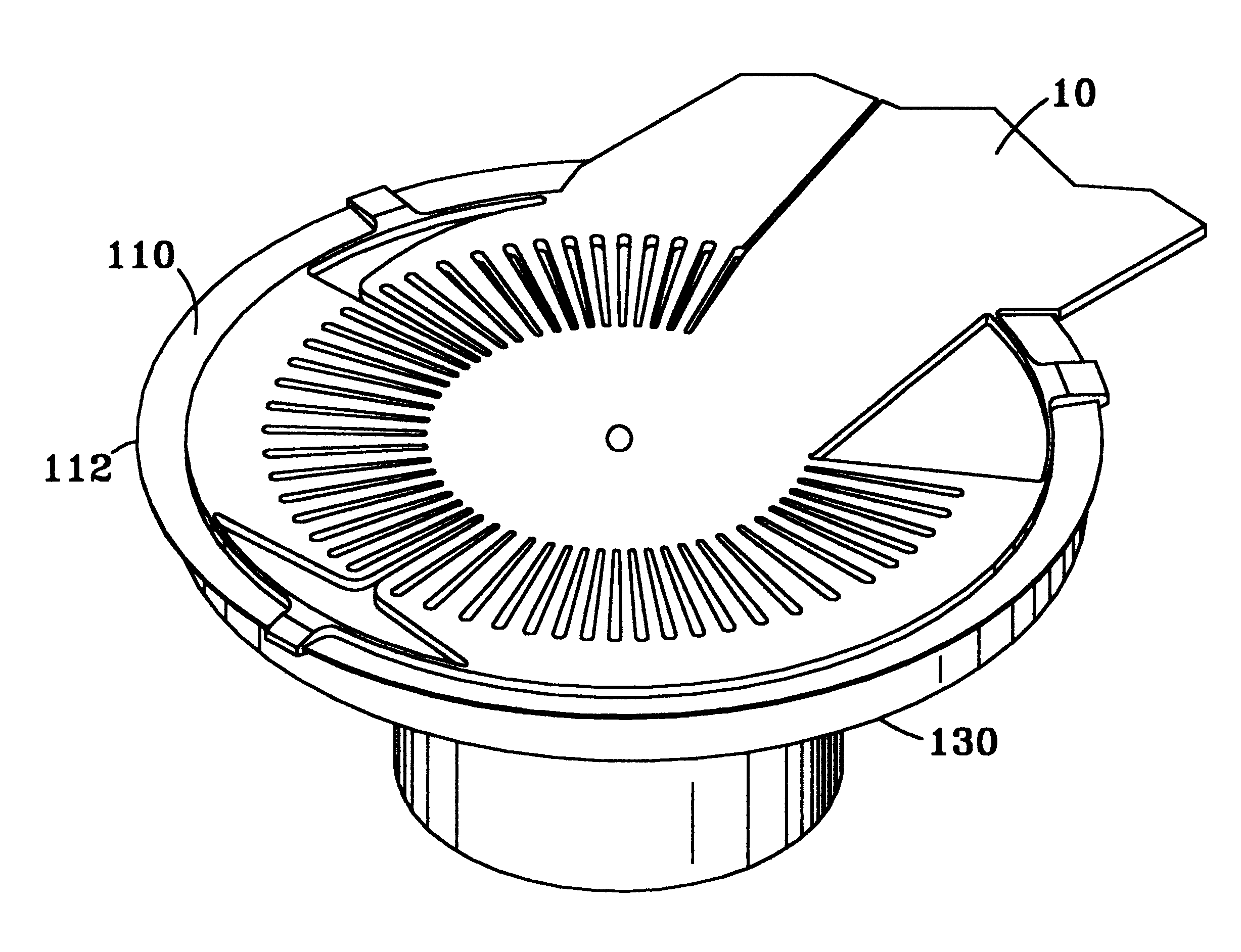
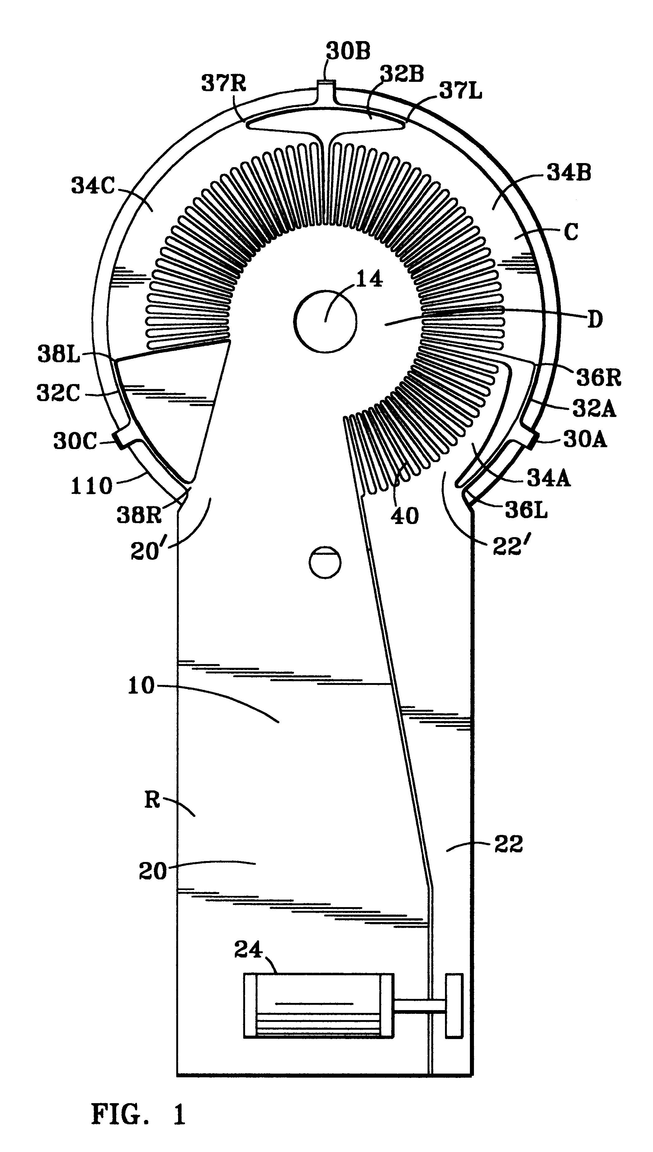
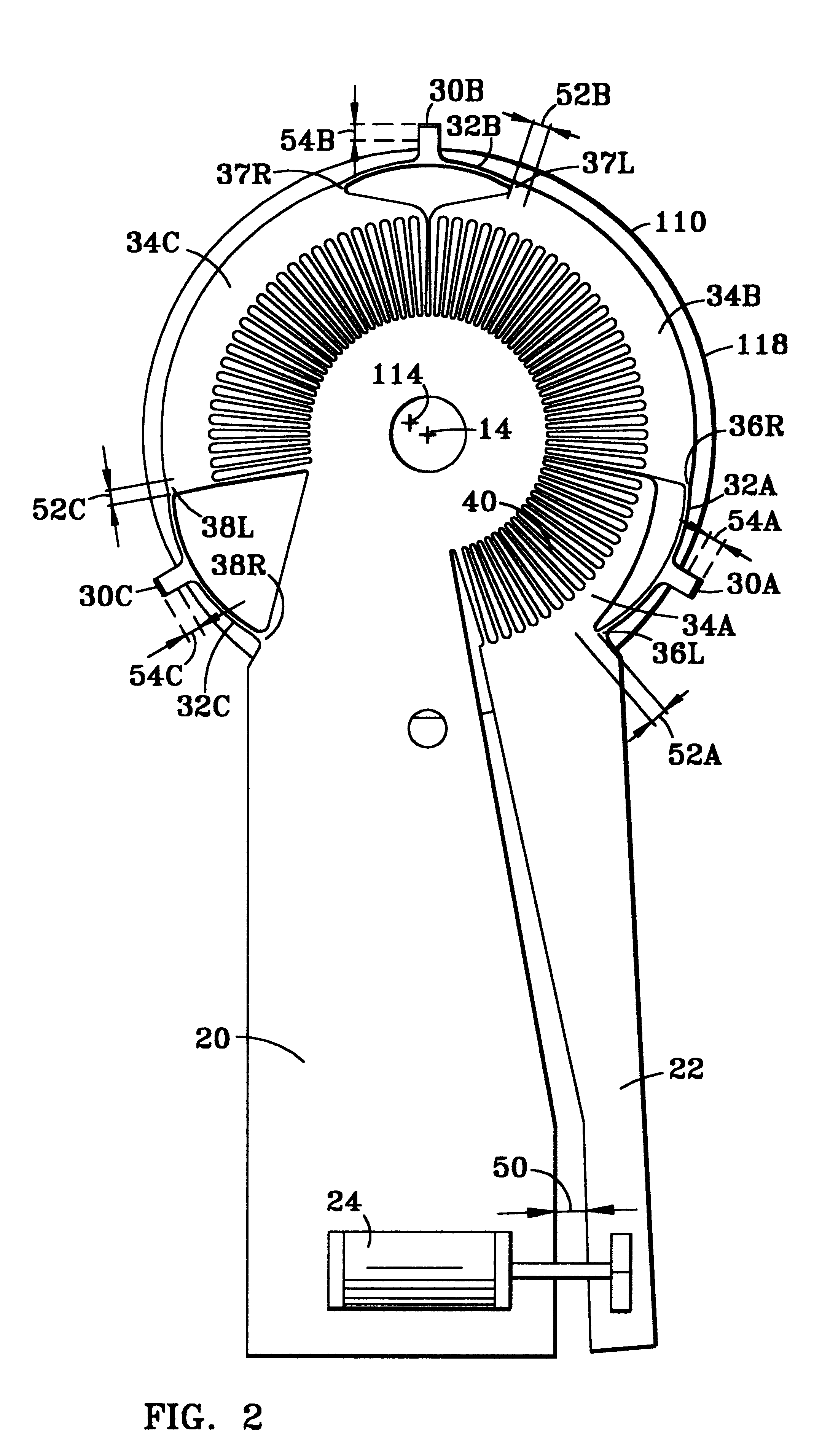
Referring to FIGS. 1 and 2, the invention embodies an end-effector holder 10 that holds a circular disc workpiece 110, for example, between a plurality of peripherally radially extending fingers 30, shown as three equilaterally circumferentially spaced finger holders, that receive and contact the workpiece. Referring to FIGS. 3-5, it can be seen that the fingers 30 are preferably recessed, receiving and contacting the workpiece along their interior surfaces 72. Different configurations are desirable for different applications as will be later discussed.

In the form shown in FIGS. 1 and 2, the holder 10 is a thin, planar flexible sheet formed with a substantially circular section C having a rectangular section R longitudinally extending (upwardly in the drawings) from a circumference region of the circular section C, as a one-piece structure. The circular section C itself is provided with a central circular disc portion D centered at 14, surrounded by a concentric annular ring made up...


PUM


Abstract

A novel technique and apparatus for receiving, holding and/or transporting thin planar workpieces and the like that involves radially supporting circumferentially spaced thin and flexible annular ring sectors about a fixed planar central circular disc upon which the workpiece is to be received, and by limitedly rotationally bending the ring sectors about the disc, causing circumferential leaf springs bridging the successive ring sectors and carrying workpiece holding fingers to deform and thereby expand (or retract) the radial position of the fingers to accommodate the edges of the workpiece.

Description

The present invention relates to techniques and apparatus for holding, handling and transporting thin workpieces; being more specifically concerned with flat pieces such as semiconductor wafers, magnetic recording discs, flat panel displays and other thin and flat workpieces, particularly, though not exclusively, as they may be handled and transported between workstations or wafer cassettes and the like.BACKGROUND OF INVENTIONThe art is replete with many types of such handling mechanisms, including apparatus specifically designed for holding workpieces like semiconductor wafers, and transporting them between workstations and or wafer cassettes. Among these are mechanisms using an annular ring member to position a wafer and an annular flange or lip to support the workpieces, as suggested, for example, in U.S. Pat. No. 4,584,045, as part of a dry processing system. U.S. Pat. No. 4,749,330 discloses a simpler version of such a means, eliminating the annular positioning ring. In U.S. Pa...

Claims


Application Information

Patent Timeline
Patent Type & Authority Patents(United States)
IPC IPC(8): H01L21/67H01L21/687
CPCH01L21/68707Y10S414/141
Inventor KEIGLER, ARTHUR
Owner HERCULES TECH GROWTH CAPITAL
Why Eureka
Try Eureka