Passenger's weight measurement device for vehicle seat and attachment structure for load sensor

a technology for vehicle seats and weight measurement devices, which is applied in the direction of roofs, movable seats, transportation and packaging, etc., can solve the problems of low distortion, large number of components such as linking members, and difficulty in accurately measuring the passenger's weight, so as to suppress the generation of initial loads

Inactive Publication Date: 2008-11-25
HONDA MOTOR CO LTD
View PDF42 Cites 69 Cited by
  • Summary
  • Abstract
  • Description
  • Claims
  • Application Information

AI Technical Summary

Benefits of technology

[0011]In connection with the first problem, it is an object of the present invention to provide a passenger's weight measurement device for a vehicle seat, and an attachment structure for a load sensor, capable of suppressing generation of an initial load.
[0012]In connection with the second problem, it is another object of the present invention to provide a passenger's weight measurement device which includes a pair of slide rails and load cells arranged at four corners of the slidable seat and which can prevent interference with load measurement of the load cells.

Problems solved by technology

However, when the passenger's weight measurement device is assembled, when the vehicle seat is fixed to the passenger's weight measurement device, and when the passenger's weight measurement device is fixed to the vehicle floor or the like, a dimension error or an assembling position error occurs to cause very low distortion.
Because an initial load is applied to the load sensor by the distortion, there is a first problem that it is difficult to accurately measure the passenger's weight.
However, the passenger's weight measurement device disclosed in JP A 11-304579 has a problem that the large number of components such as a linking member is increased because the pair of slide rails and the seat bracket fixed to the vehicle body floor side are linked together by a parallelogram linking mechanism.
Because the parallelogram linking mechanism is disposed between the pair of slide rails and the seat bracket, there is a problem that it is difficult to set a height from the vehicle body floor to an upper surface of the seat cushion equal to or less than a certain height.
However, generally it is difficult to accurately fix the pair of slide rails and the like to the vehicle body floor side.
Further, it is difficult to maintain a facing distance between the pair of side frames because of the seat sliding.
In this structure, there is a second problem that an unnecessary force is applied on the load cell to interfere with passenger's load measurement.

Method used


Image

  • Passenger's weight measurement device for vehicle seat and attachment structure for load sensor
  • Passenger's weight measurement device for vehicle seat and attachment structure for load sensor
  • Passenger's weight measurement device for vehicle seat and attachment structure for load sensor

Examples


first embodiment

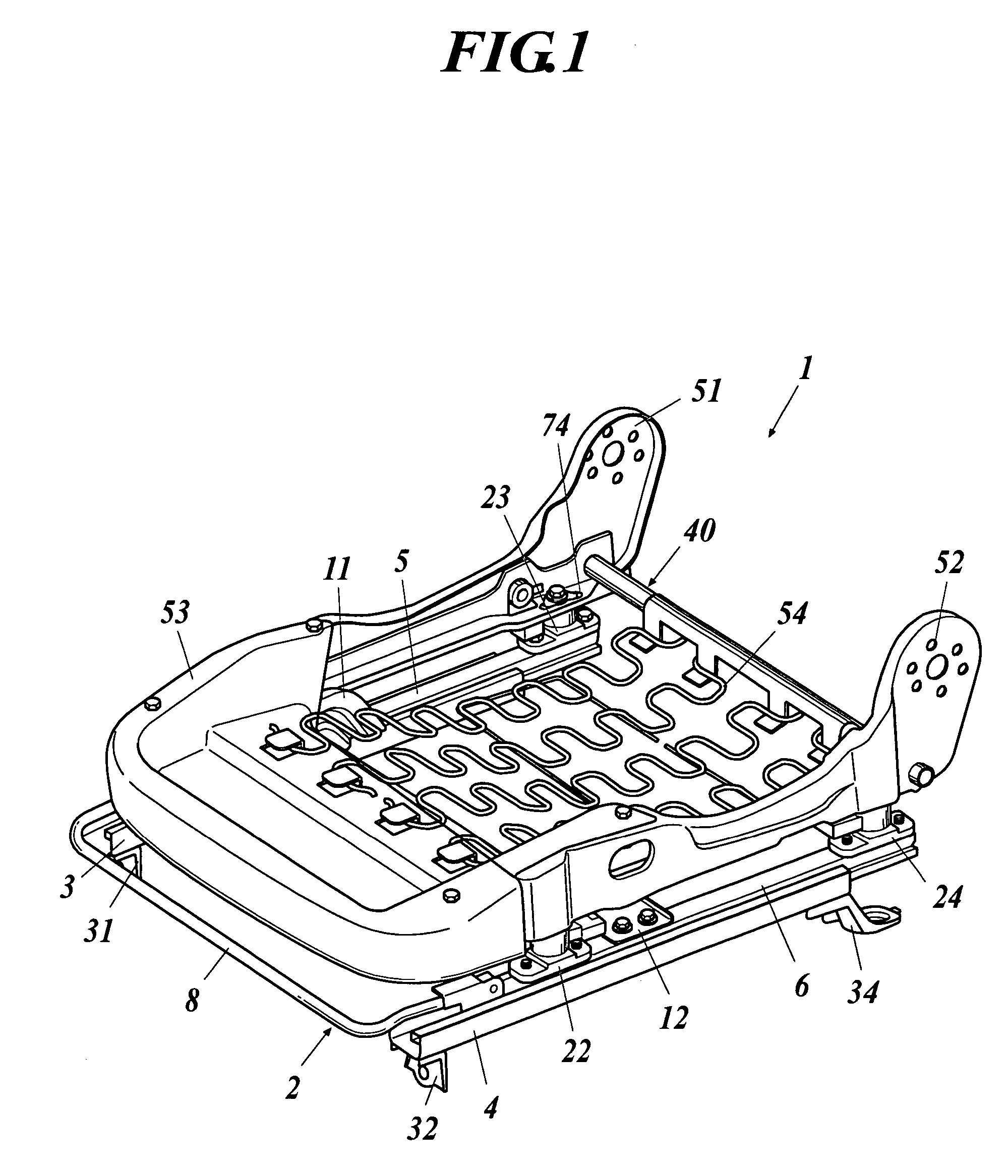
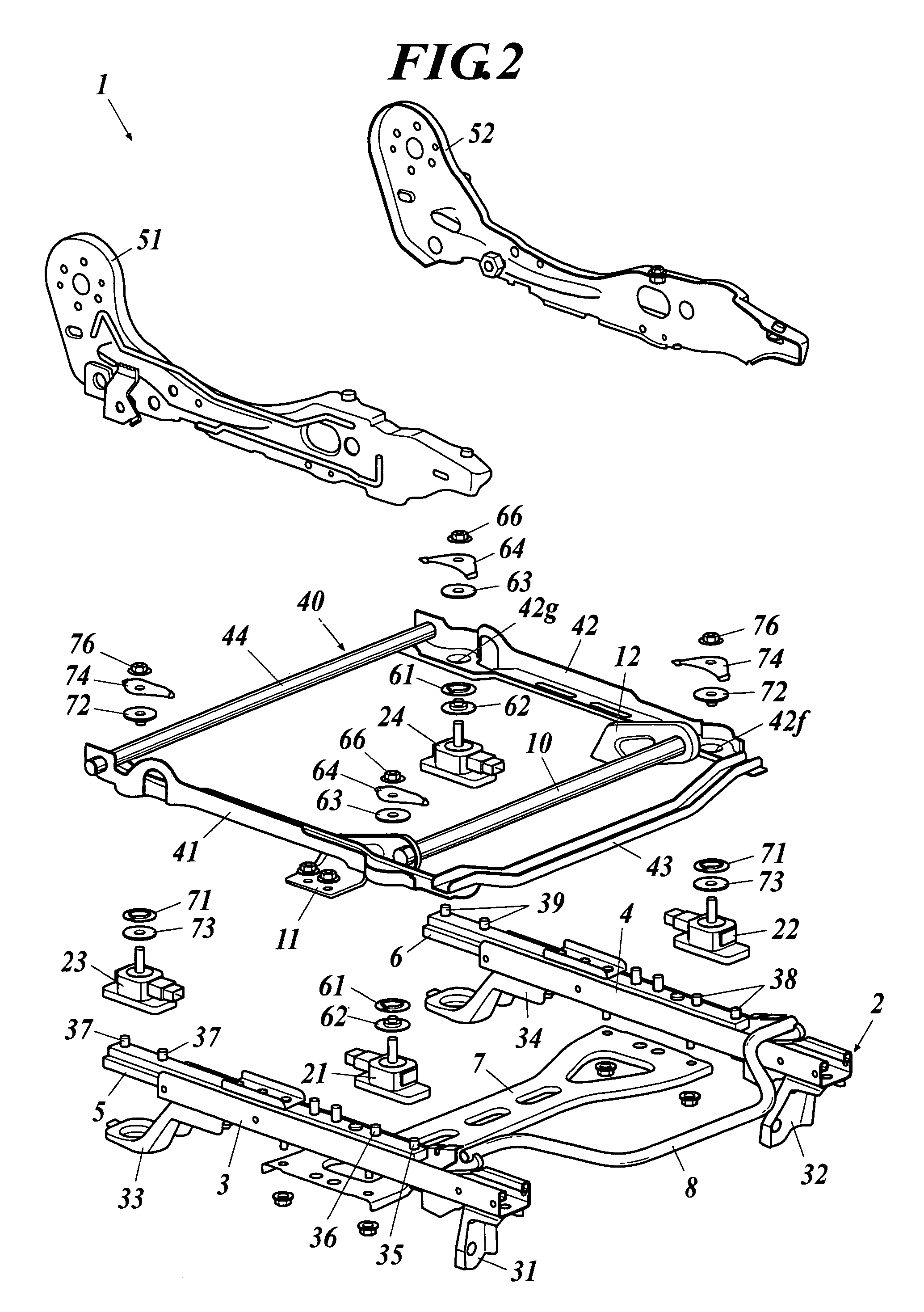
[0066]FIG. 1 is a perspective diagram of a passenger's weight measurement device 1 for a vehicle seat, and FIG. 2 is an exploded perspective diagram of the passenger's weight measurement device 1.

[0067]As shown in FIGS. 1 and 2, a slide adjuster 2 for adjusting a back-and-forth position of the vehicle seat is mounted to a floor of a passenger's room. The slide adjuster 2 includes lower rails 3 and 4 disposed in parallel with each other, an upper rail 5 engaged with the lower rail 3 to slide back and forth on the lower rail 3 with respect to the same, an upper rail 6 engaged with the lower rail 4 to slide back and forth on the lower rail 3 with respect to the lower rail 4, a lower bracket 7 fixed to bottom surfaces of the lower rails 3 and 4 by bolts and nuts or rivets to bridge a gap therebetween, a lock mechanism 8 for locking / unlocking the upper rails 5 and 6 to / from the lower rails 3 and 4, brackets 31 and 33 fixed to the bottom surface of the lower rail 3, and brackets 32 and 34...

second embodiment

[0103]FIG. 11 is an exploded perspective assembly diagram showing a passenger's weight measurement device according to a second embodiment. FIG. 12 is an exploded perspective assembly diagram of a seat section including the passenger's weight measurement device of the second embodiment. FIG. 13 is a perspective appearance diagram showing the passenger's weight measurement device of the second embodiment. FIG. 14 is a perspective appearance diagram showing a schematic configuration of the passenger's weight measurement device of the second embodiment. FIG. 15 is a perspective appearance diagram showing the passenger's weight measurement device of the second embodiment. FIG. 16 is a longitudinal sectional diagram of an enlarged main section of FIG. 15. FIG. 17 is a plan diagram of an enlarged main section of FIG. 16.

[0104]FIG. 18 is a longitudinal sectional diagram of a first elastic bushing applied to the passenger's weight measurement device of the second embodiment. FIG. 19 is a lo...


PUM


Abstract

There is disclosed a passenger's weight measurement device for a vehicle seat, capable of suppressing generation of an initial load. The passenger's weight measurement device includes an upper rail disposed to be movable back and forth on a lower rail fixed to a vehicle floor; a load sensor fixed on the upper rail; and a frame disposed on the load sensor and below a vehicle seat, wherein a rod extends from the load sensor to penetrate the frame and to be inserted into an insertion hole formed in a center of a leaf spring, the leaf spring is curved into an angle shape to separate the center of the leaf spring from the frame, a nut is engaged with the rod on the leaf spring, and both hems of the leaf spring abut on the frame in a state that the leaf spring is fastened by the nut.

Description

[0001]The present disclosure claims priority to Japanese Patent Application No. 2005-264128 to Tokugan filed on Sep. 12, 2005, Japanese Application No. 2005-268465 to Tokugan filed on Sep. 15, 2005 and Japanese Application No. 2005-264002 to Tokugan filed on Sep. 12, 2005, the entire disclosures of which are herein incorporated by reference in their entirety.BACKGROUND OF THE INVENTION[0002]1. Field of the Invention[0003]The present invention relates to a passenger's weight measurement device for vehicle seat, for measuring a weight of a passenger of a vehicle seat, and an attachment structure for attaching a load sensor to the passenger's weight measurement device.[0004]2. Description of the Related Art[0005]Recently, to improve performance of various safety devices such as a seat belt and an air bag, operations of the safety devices have been controlled in accordance with a weight of a passenger sitting on a vehicle seat in some cases. In the conventional passenger's weight measur...

Claims


Application Information

Patent Timeline
Patent Type & Authority Patents(United States)
IPC IPC(8): B60N2/42
CPCB60N2/002B60N2/06B60N2/4263
Inventor ENDO, SHIGERUSATO, KENJINISHIDE, HARUTOMIYAMAZAKI, TATSUYAKUMAKIRI, NAOTAKAKOJIMA, MIKIHITOYOSHIFUKU, MASASHIFURUKAWA, TAKASHI
Owner HONDA MOTOR CO LTD
Why Eureka
Try Eureka