
Glass film coating device and bottom plate die set

A technology of coating device and bottom plate, which is applied to discharge tubes, electrical components, circuits, etc., can solve problems such as affecting effective production time, and achieve the effect of improving effective production time and avoiding downtime for maintenance.

Active Publication Date: 2014-03-26
CSG HOLDING
View PDF3 Cites 6 Cited by
  • Summary
  • Abstract
  • Description
  • Claims
  • Application Information

AI Technical Summary

Problems solved by technology

This greatly affects the effective production time

Method used


Image

  • Glass film coating device and bottom plate die set
  • Glass film coating device and bottom plate die set
  • Glass film coating device and bottom plate die set

Examples


Embodiment Construction

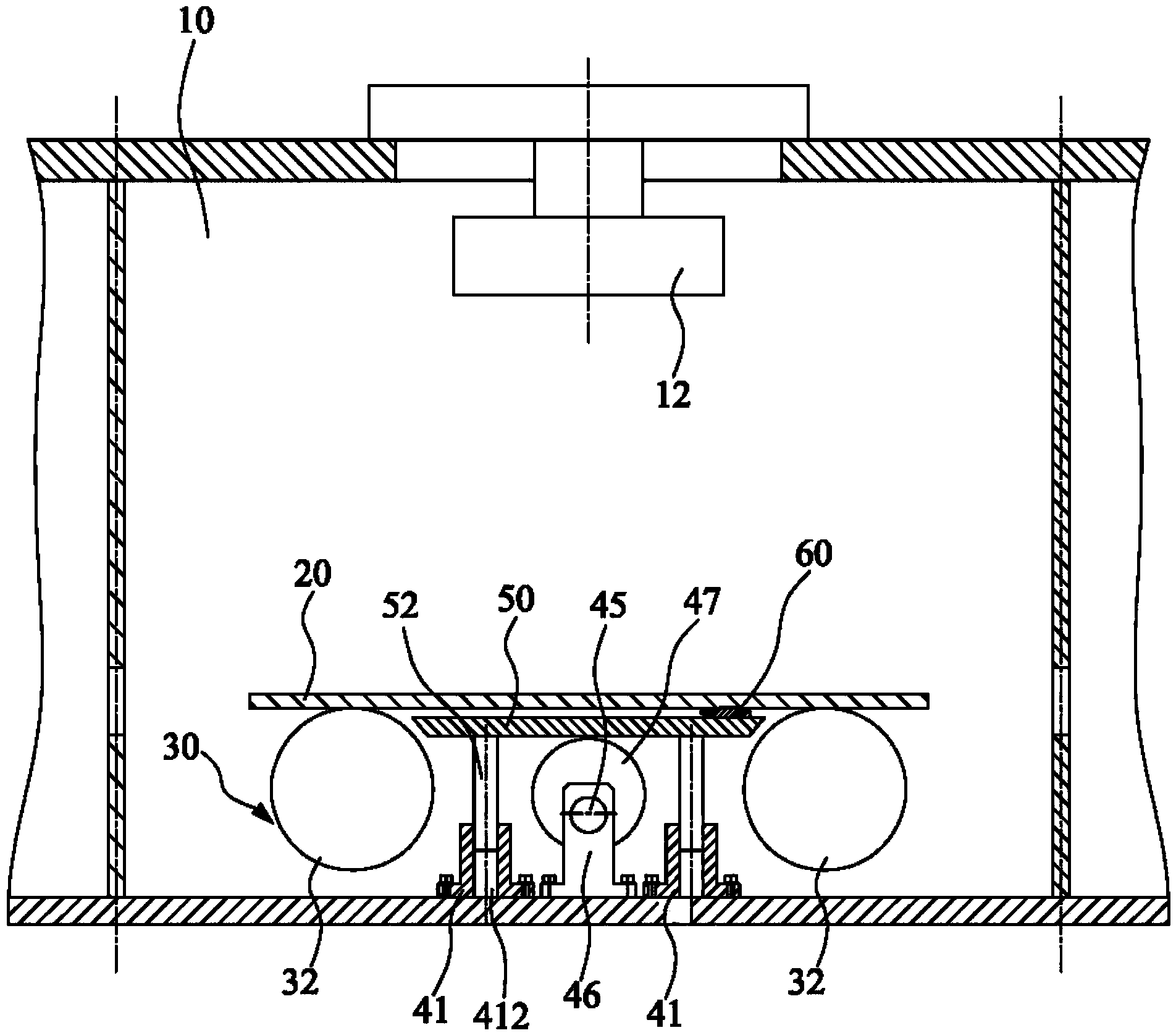
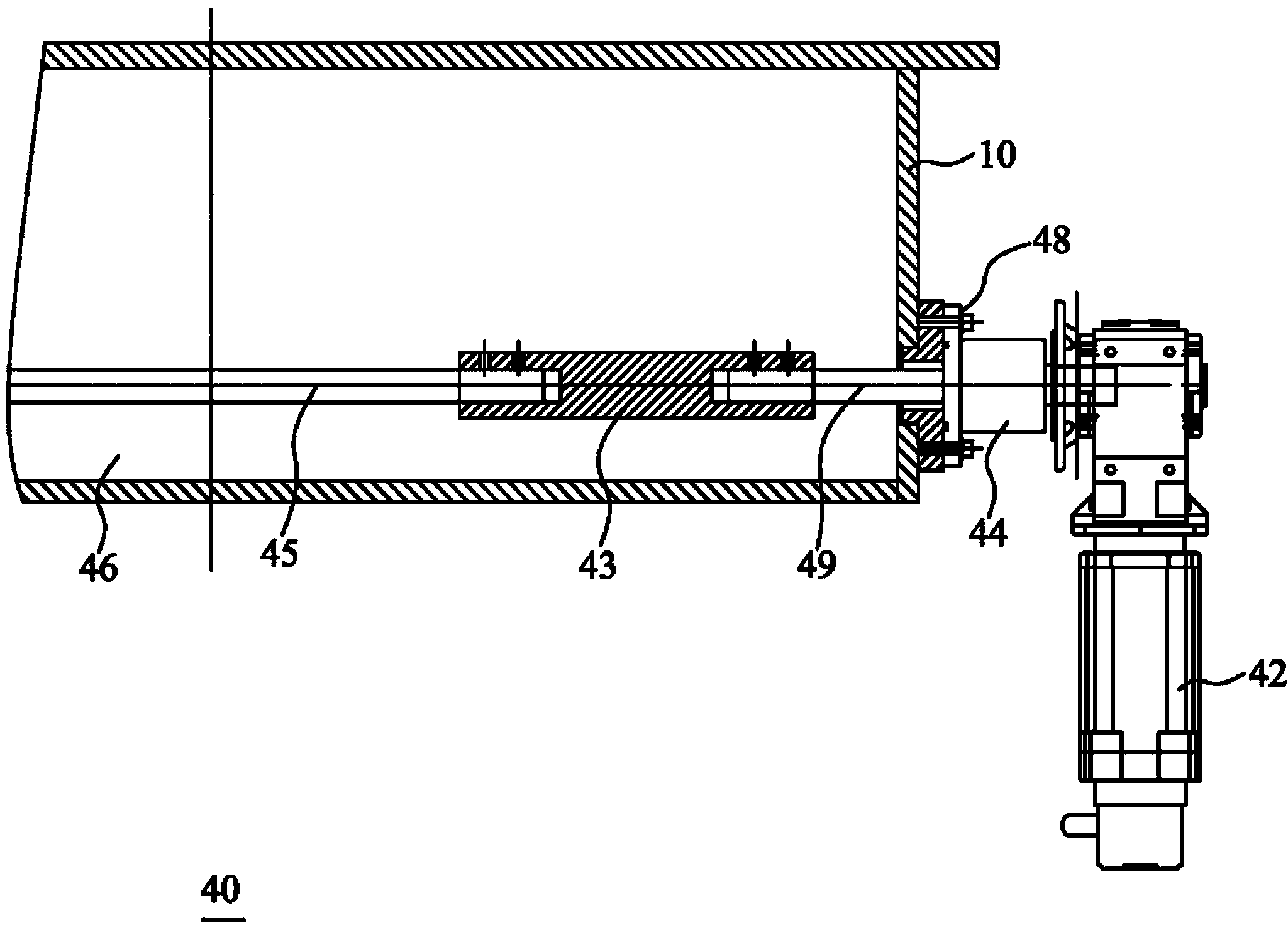
[0022] The glass coating device and its bottom plate module of the present invention will be further described in detail with reference to the accompanying drawings and embodiments.

[0023] See figure 2 , image 3 , a kind of glass coating device of the embodiment of the present invention, it is used for coating the glass 20 to be coated, this glass coating device comprises coating chamber 10, transmission unit 30 and base plate module, and this transmission unit 30 is positioned at this coating cabin 10 lower end, The conveying unit 30 includes a plurality of rollers 32, the bottom plate module is arranged between the rollers 32, the glass to be coated 20 is delivered to the coating chamber 10 through the rollers 32, the bottom plate module includes a bottom plate 50 and Lifting element 40, this lifting element 40 links to each other with this base plate 50, thereby regulates the relative distance between this base plate 50 and this to-be-coated glass 20 by this lifting el...


PUM


Abstract

The invention relates to a glass film coating device which is used for coating to-be-film-coated glass with a film and comprises a film coating cabin, a transmission unit and a bottom plate die set, wherein the transmission unit is positioned at the lower end of the film coating cabin and comprises a plurality of roller ways; the bottom plate die set is arranged among the roller ways; the to-be-film-coated glass is transmitted to the film coating cabin through the roller ways; the bottom plate die set comprises a bottom plate and a lifting element; the lifting element is connected with the bottom plate, so as to adjust the relative distance between the bottom plate and the to-be-film-coated glass. The invention further provides the bottom plate die set of the glass film coating device. According to the glass film coating device, as the bottom plate has the characteristic of being liftable in a vacuum chamber, and when the cumulate film thickness is increased, the bottom plate can be adjusted downwards so as to enable the thickened film not to affect the to-be-film-coated glass. As a result, halt overhaul is avoided, and the effective production time is greatly increased. The glass film coating device can be widely applied to a continuous glass film coating production line.

Description

technical field [0001] The invention relates to a film coating device, in particular to a glass film coating device and its base plate module. Background technique [0002] In recent years, with the increase of national energy conservation and emission reduction and people's awareness of low-carbon environmental protection, the application of energy-saving glass in doors, windows and glass curtain walls has become more and more extensive. In the sputtering coating production line for the production of energy-saving glass, the cathode is continuously sputtering. Since the size of the glass to be coated is different, and there is a distance between the glass and the glass, the bottom plate under the cathode slowly begins to accumulate film layers. , in continuous production for about one month, the film layer accumulated on the bottom plate will be very thick and will be higher than the bottom surface of the glass. Make it run obliquely at the bottom plate, or the accumulated...

Claims


Application Information

Patent Timeline
Patent Type & Authority Applications(China)
IPC IPC(8): C03C17/00
CPCH01J37/32715H01J37/32733H01J37/32752H01J37/34H01L21/68742
Inventor 陈海峰白振中
Owner CSG HOLDING
Learn More