Al technical title is built by PatSnap Al team. It summarizes the technical point description of the patent document.
A coding line and laser technology, used in detonators, offensive equipment, etc., to achieve the effect of improving coding speed, ensuring coding quality, and high production efficiency
Inactive Publication Date: 2016-04-20
HUNAN SHENFU GRP XIANGHONG MACHINERY CHEM
View PDF4 Cites 0 Cited by
Summary
Abstract
Description
Claims
Application Information
AI Technical Summary
This helps you quickly interpret patents by identifying the three key elements:
Problems solved by technology
Method used
Benefits of technology
Problems solved by technology
[0002]
From 2002 to 2005, the laser coding of industrial detonators adopted the coding mode of Shenzhen Han’s Laser Company, that is, a long magnetic cylinder (1200mm) was used to send the mold with the detonator to the laser coding area, and then the magnetic cylinder (500mm) hooked it to the laser coding table. After the two ends of the laser table were closed, the laser began to code the detonators. Nine actions, many control actions, the spring hook on the hook mold cylinder is easy to break, and needs to be replaced every two days, and the mold is often not hooked in place, which seriously affects the coding quality and coding efficiency of the detonator
And during laser coding, use the cylinder to directly push or hook the mold with 50 rounds of detonators. The inertia is large. The collision of the mold will make the detonators in the mold jump out of the mold. It is easy to be detonated by the laser, causing the detonator of the mold to explode. If the explosion cannot be vented, it will cause the detonator on the belt line to explode and cause devastating damage to the laser marking head. Every time the laser coding explosion occurs, the laser head is almost blown up, and the loss is about 30,000 yuan
In short, the past detonator coding method resulted in low coding efficiency, and the shift output was only 40,000 rounds; the coding quality was poor, the coding handwriting was blurred, the depth of the notch was not up to standard, and the safety hazard was great.
Method used
Image
Click on the blue label to locate the original text in one second.
Reading with bidirectional positioning of images and text.
Examples
Embodiment Construction
[0015] Further illustrate the present invention below in conjunction with accompanying drawing.
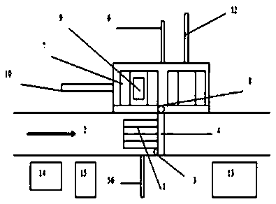
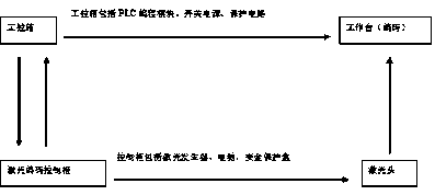
[0016] The invention is a detonator laser coding line, which is characterized in that it includes a coding mold 1, an antistatic belt 2, a bar 4, an upper mold photoelectric tube 3, an upper mold cylinder 5, a positioning cylinder 6, a safety door cylinder 8, and a laser coding head 9. Horizontal pushing magnetic cylinder 10, lower mold photoelectric tube 11, lower mold cylinder 12, laser control cabinet 13, industrial control box 14, air source 15; the laser control cabinet 13 includes the main control box, laser power supply box, laser head, computer , Safety protection box; Industrial control box includes PLC programmer, switching power supply, and protection circuit.
[0017] Further, hollow out under the coding workbench 7, when a detonator explodes accidentally, the energy can be released from the hollowed out bottom, while the upper part of the coding workbench 7 is designe...
PUM
Abstract
The invention discloses a primer laser coding line which is characterized by comprising an antistatic strap, a coding worktable, a coding mold, a barrier strip, an upper mold photoelectric tube, an upper mold cylinder, a positioning cylinder, a safety gate (AND gate) cylinder, a laser coding head, a horizontal pushing magnetic cylinder, a lower mold photoelectric tube, a lower mold cylinder, a laser control cabinet and a gas source, wherein the laser control cabinet comprises a main control box, a laser power supply box, a laser head, a computer and a safety protection case; an industrial control box comprises a PLC (programmable logic controller) programmer, a switching power supply and a protection circuit; and the inside of the laser control cabinet is additionally provided with the safety protection case in which laser power overload protection, X and Y galvanometer motor deflection shutdown protection, laser time protection and filtration stray current protection are set. In case of an abnormal condition, a laser power supply is automatically cut off, thus ensuring coding safety. The primer laser coding line prevents accidental explosion in the coding process, and achieves the purposes of stability, high quality, reliability, safety and high production efficiency in laser coding.
Description
technical field [0001] The invention relates to the field of mechanical equipment, in particular to a detonator laser coding line. Background technique [0002] From 2002 to 2005, the laser coding of industrial detonators adopts the coding mode of Shenzhen Han’s Laser Company, that is, the mold equipped with detonators is sent to the laser coding area with a long magnetic cylinder (1200mm), and then hooked to the laser coding by a magnetic cylinder (500mm) On the stage, after the two ends of the laser table are closed, the laser starts to code the detonator. After coding, the original route returns to the belt transportation line, and the next model of detonator can enter the code on the coding table. Die coding requires nine actions and many control actions. The spring hook on the mold hook cylinder is easily damaged and needs to be replaced every two days, and the mold often does not hook properly, which seriously affects the coding quality and coding efficiency of the det...
Claims
Application Information
Patent Timeline
Application Date:The date an application was filed.
Publication Date:The date a patent or application was officially published.
First Publication Date:The earliest publication date of a patent with the same application number.
Issue Date:Publication date of the patent grant document.
PCT Entry Date:The Entry date of PCT National Phase.
Estimated Expiry Date:The statutory expiry date of a patent right according to the Patent Law, and it is the longest term of protection that the patent right can achieve without the termination of the patent right due to other reasons(Term extension factor has been taken into account ).
Invalid Date:Actual expiry date is based on effective date or publication date of legal transaction data of invalid patent.