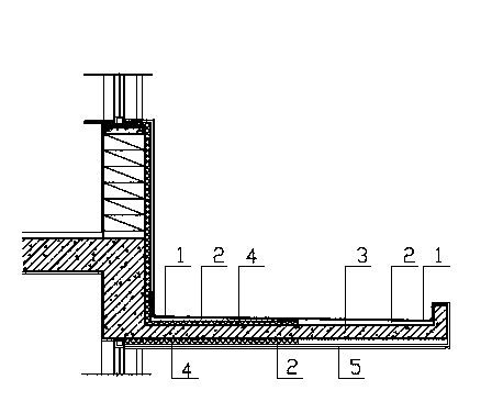
Horizontal plate thermal bridge structure

A technology of horizontal plates and thermal bridges, applied in the direction of building components, heat preservation, etc., can solve the problem of not considering the relationship between the length of the heat preservation plate and the horizontal plate, and achieve the effect of saving heat preservation materials and cost

Inactive Publication Date: 2014-03-26
陈祥凤
View PDF0 Cites 0 Cited by
  • Summary
  • Abstract
  • Description
  • Claims
  • Application Information

AI Technical Summary

Problems solved by technology

The relationship between the insulation board and the length of the horizontal board is not considered

Method used


Image

  • Horizontal plate thermal bridge structure

Examples


Embodiment Construction

[0009] like figure 1 As shown, for the thermal bridge structure of the horizontal plate, within the range of the non-condensing thermal resistance length, use 1:3 cement mortar to level the unevenness of the horizontal plate, paste insulation materials, and press 4 mm polymer mortar on the insulation materials. Into the grid cloth, 20 mm waterproof mortar to find a 1% slope. Waterproof mortar returns 250 along the exterior wall. Paste thermal insulation material under the horizontal board, use 4 mm polymer mortar to press into the grid cloth under the thermal insulation material, and paint. Outside the length range of non-condensing thermal resistance, apply waterproof mortar on the horizontal board to find a 1% slope, and the thickness shall be in line with the place where there is insulation material. Under the horizontal board, apply 1:3 cement mortar and paint the finish layer.


PUM


Abstract

The invention discloses a thermal bridge structure, and particularly relates to a horizontal plate thermal bridge structure. The horizontal plate thermal bridge structure is composed of a first waterproof mortar layer, a first polymer mortar gridding cloth, a first insulation board, a reinforced concrete plate, a second insulation board, a second polymer mortar gridding cloth, a second waterproof mortar layer and a finish coat. When a horizontal plate is too long and is larger than a length which meets the condition of non-condensate heat resistance, the part, beyond the length range corresponding to the requirement of the non-condensate heat resistance, of the horizontal plate is not insulated.

Description

technical field [0001] The invention relates to a thermal bridge structure, in particular to a horizontal plate thermal bridge structure. Background technique [0002] At present, building energy conservation has been fully implemented as a national policy across the country. As one of the energy-saving measures, building external insulation is generally adopted. The horizontal plate connected to the heating room is the heat bridge part of the external heat preservation. The usual technical measure is to stick insulation boards up and down the horizontal plate to block the heat bridge. The relationship between the insulation board and the length of the horizontal board is not considered. Contents of the invention [0003] The object of the present invention is to overcome the above disadvantages and provide a horizontal plate thermal bridge structure. The thermal bridge structure of the horizontal slab consists of waterproof mortar, polymer mortar mesh cloth, insulation ...

Claims


Application Information

Patent Timeline
Patent Type & Authority Applications(China)
IPC IPC(8): E04B1/76E04B1/80
Inventor 陈祥凤
Owner 陈祥凤
Why Eureka
Try Eureka