Brush making machine and method used for reducing vibration

A brush making machine and movement technology, applied in the field of vibration caused by movement, can solve problems such as limited vibration bandwidth, and achieve the effect of eliminating vibration

Inactive Publication Date: 2014-03-26
ZAHORANSKY AG
View PDF7 Cites 3 Cited by
  • Summary
  • Abstract
  • Description
  • Claims
  • Application Information

AI Technical Summary

Problems solved by technology

The disadvantage of this passive cancellation is that

Method used


Image

  • Brush making machine and method used for reducing vibration
  • Brush making machine and method used for reducing vibration
  • Brush making machine and method used for reducing vibration

Examples


Embodiment Construction

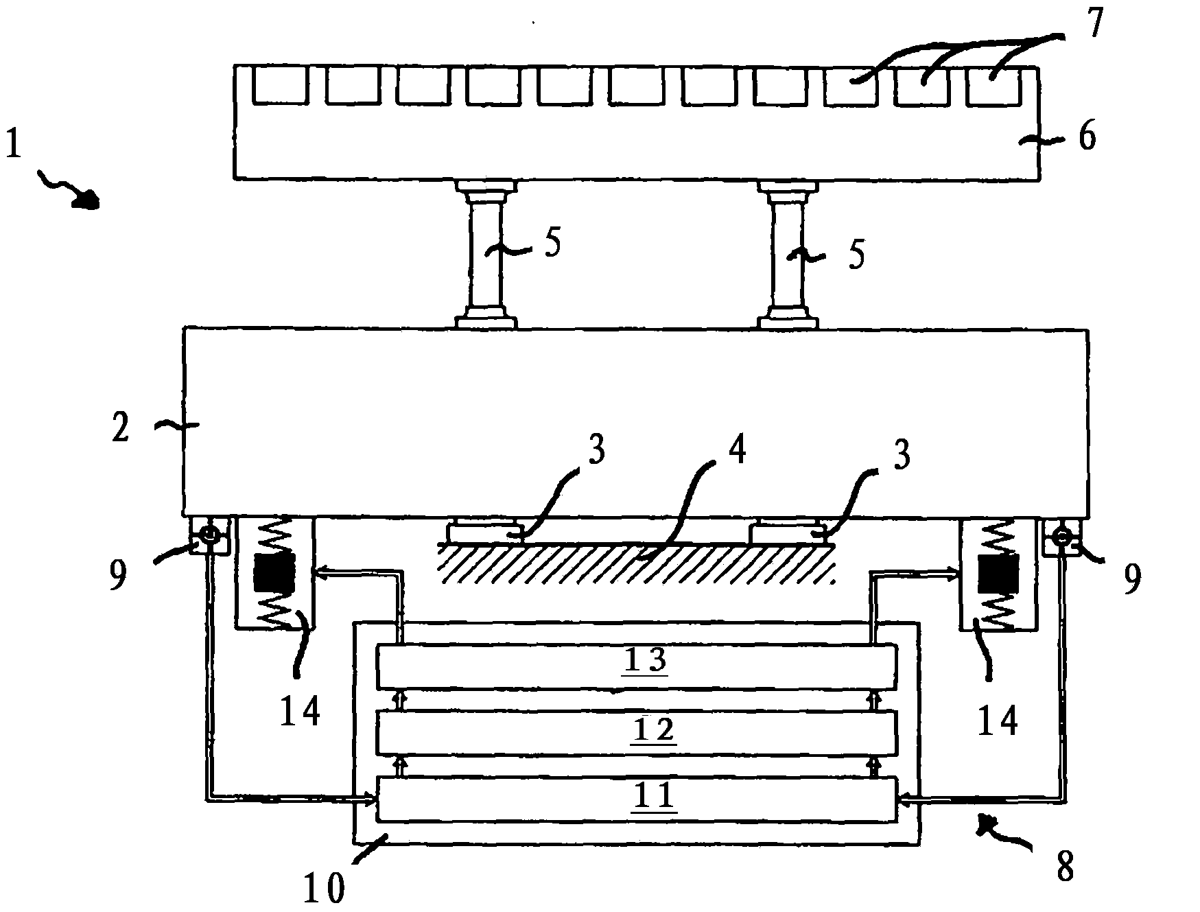
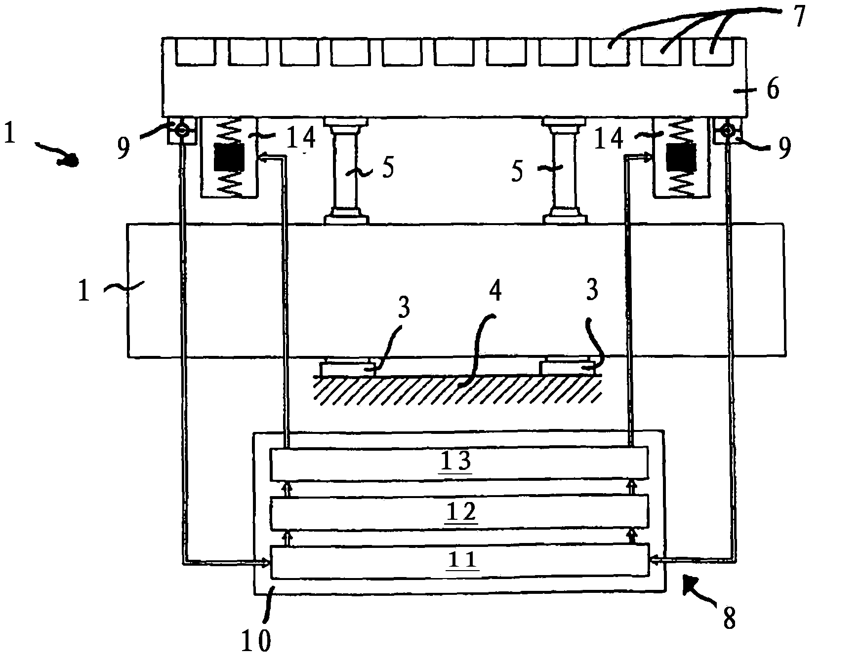
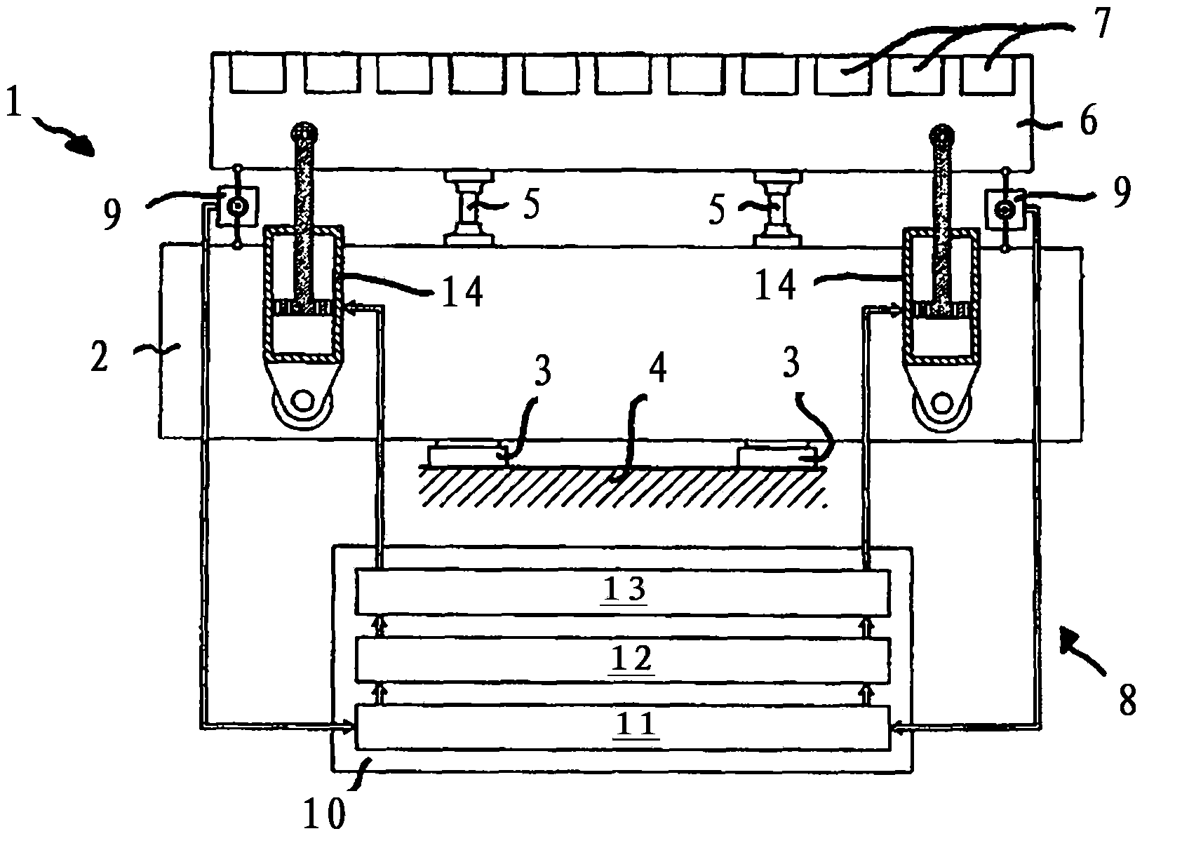
[0022] according to figure 1 The brush-making machine denoted as a whole by the reference numeral 1 comprises a base part 2 which is set up on the ground 4 by means of feet 3 . The base part 2 is connected via connecting elements 5 to a functional unit 6 which has a plurality of functional elements 7 . The respective functional part 7 forms a differently movable part of the brush making machine 1 , for example a caulking tool or a positioning device for the brush body. Various vibrations generated by each functional part 7 are transmitted to the functional unit 6 . Depending on the stiffness of the connection part 5 , these vibrations are damped or transmitted to the base part 2 between the functional unit 6 and the base part 2 . A part of the transmitted vibration is in turn damped by the foot 3 relative to the ground 4 . The remaining vibrations are absorbed and eliminated or at least reduced by the device 8 . For this purpose, the device 8 has sensors 9 arranged on the ...


PUM


Abstract

The present invention relates to a brush making machine (1), comprising at least one movable function part (7) and a device (8) used for reducing vibration caused by movement of the function part (7). The device (8) is configured for actively eliminating and/or actively damping vibration. The present invention also relates to a method used for reducing vibration caused by movement of the function part (7) of the brush making machine (1), so as to reduce the vibration by actively eliminating and/or actively damping the vibration.

Description

technical field [0001] The invention relates to a brush-making machine comprising at least one movable functional part and a device for reducing vibrations due to the movement of the functional part, and to a brush-making machine for reducing method of vibration caused by motion. Background technique [0002] In brushmaking machines as well as in mechanical construction there is generally the problem of vibrations caused by movable parts which can affect the reliable operation of the machine or the quality of the object to be produced. Efforts are therefore made to eliminate, compensate or reduce these vibrations. The brush-making machine has a number of moving parts which perform periodic movements, where not only linear movements but also inclined or right-angled movements between two components are possible. There are also components whose mass decreases or increases over time, such as material boxes or brush storage boxes. The bandwidth of the natural frequencies of s...

Claims


Application Information

Patent Timeline
IPC IPC(8): F16F15/02F16F15/023F16F15/03A46D3/00
CPCA46D3/04A46D3/08F16F15/02
Inventor G·佐默
Owner ZAHORANSKY AG
Why Eureka
Try Eureka