
Gear shift control system for automatic transmission

A technology of automatic transmission and control system, applied in transmission control, motor vehicles, hybrid vehicles, etc., can solve problems such as lack of braking force, and achieve the effect of promoting ease, low cost, and improving accuracy

Inactive Publication Date: 2014-03-26
SUZUKI MOTOR CORP
View PDF8 Cites 7 Cited by
  • Summary
  • Abstract
  • Description
  • Claims
  • Application Information

AI Technical Summary

Problems solved by technology

This can cause the automatic transmission to undesirably upshift or downshift based on the relationship between vehicle speed and accelerator pedal position, which can result in a lack of braking power when the vehicle suddenly begins to decelerate during acceleration

Method used


Image

  • Gear shift control system for automatic transmission
  • Gear shift control system for automatic transmission
  • Gear shift control system for automatic transmission

Examples


Embodiment Construction

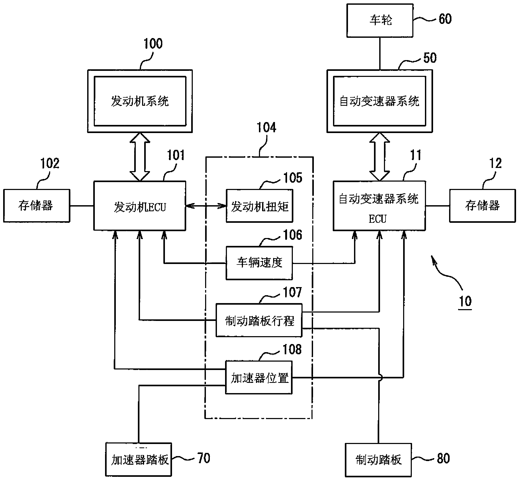
[0039] Embodiments will be described below with reference to the drawings. Figure 1 to Figure 7 The shift control system 10 of the automatic transmission according to the first embodiment will be described.

[0040] The transmission control system 10 is designed to control the operation of an automatic transmission mounted on a motor vehicle together with an internal combustion engine. The automatic transmission automatically changes the speed of the drive shaft of the internal combustion engine and transmits the torque of the drive shaft to the transaxle of the wheels 60 to drive the vehicle.

[0041] The internal combustion engine referred to herein is configured to combust a mixture of air and fuel injected into a combustion chamber to reciprocate a piston, thereby rotating a drive shaft through a crankshaft to output torque. Operation of an engine system 100 including an internal combustion engine and components or actuators such as fuel injectors is generally controlled...


PUM


Abstract

A gear shift control system for vehicles is provided which mathematically calculates a rate of deceleration of the vehicle equipped an automatic transmission upon start of deceleration of the vehicle and inhibits the automatic transmission from upshifting or changes a permissible gear shift range of the automatic transmission as a function of the rate of deceleration of the vehicle, thereby ensuring a desired degree of braking force including an engine braking force while the vehicle is decelerating.

Description

technical field [0001] This invention relates generally to shift control systems for automatic transmissions of vehicles, and more particularly to control systems designed to control the operation of automatic transmissions when deceleration of the vehicle is required. Background technique [0002] Typically, an internal combustion engine in a motor vehicle rotates within a selected one of a plurality of gear ratio ranges in order to drive the wheels of the vehicle with a desired torque. Specifically, a vehicle has an automatic transmission interposed between a drive shaft and wheels so as to provide a prescribed torque to the wheels in a low speed range or a high speed range. [0003] A typical automatic transmission automatically changes the gear ratio according to the position of the accelerator operated by the vehicle driver in relation to the vehicle speed, thereby transmitting the torque output by the internal combustion engine to the wheels. For example, if Figure 1...

Claims


Application Information

Patent Timeline
Patent Type & Authority Applications(China)
IPC IPC(8): F16H61/00
CPCB60W30/18072Y10S903/947B60W2720/106F16H61/0213F16H61/16F16H61/21F16H2061/0237F16H2061/163B60W20/30B60W10/11B60W10/18
Inventor 河本修平吉田谕广
Owner SUZUKI MOTOR CORP
Learn More