Supercharge Your Innovation With Domain-Expert AI Agents!

Light source device

A technology of light source device and light guide body, which is applied in the direction of light source, electric light source, printing device, etc., which can solve the problems of high-illuminance lighting area, poor balance of illuminance distribution, inability to form cross-sectional light distribution uniformity, etc., and achieve easy manufacturing , High uniformity of illuminance

Active Publication Date: 2017-04-12
USHIO DENKI KK
View PDF7 Cites 0 Cited by
  • Summary
  • Abstract
  • Description
  • Claims
  • Application Information

AI Technical Summary

Problems solved by technology

Therefore, even if the direct light illumination area and the indirect light illumination area are overlapped on the document loading surface, the balance of the illuminance distribution between the two is poor, so a high-illuminance illumination area with high cross-sectional light distribution uniformity cannot be formed.

Method used


Image

  • Light source device
  • Light source device
  • Light source device

Examples


Embodiment 1

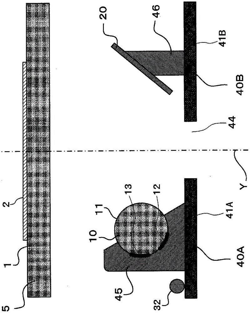
[0084] Using a white LED element as the LED element, and under the following conditions, a figure 1 The structure of the light source device (A) is shown.

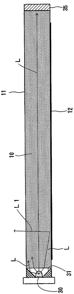
[0085]The material of the light guide is acrylic resin, the overall length is 340mm, and the diameter is 5mm. The first reflective part and the second reflective part of the light guide are constituted by a plurality of concave parts arranged along the longitudinal direction of the light guide. The depth of the above-mentioned concave part is 0.05 mm, the width of the above-mentioned concave part in the longitudinal direction of the light guide body 10 is 0.2 mm, and the separation distance between adjacent concave parts is: the indirect light side is separated by 0.4 mm to 0.6 mm in the longitudinal direction , the direct light side is separated by 0.7mm to 1.0mm in the length direction (the spacing of the concave parts is: the indirect light side is 0.6mm to 0.8mm in the length direction, and the direct light side is 0...


PUM

PropertyMeasurementUnit
Depthaaaaaaaaaa
Widthaaaaaaaaaa

Abstract

A light source device is provided. A light guide body is easy to manufacture and a high-illuminance lighting area with high uniformity of illuminance in the auxiliary scanning direction can be formed. The light source device comprises the rodlike light guide body made of light transmission material, LED elements arranged opposite to end faces in the length direction of the light guide body, and a reflector arranged parallel to the light guide body and reflecting light from the light guide body to a manuscript holding surface. The cross section, which is vertical to the length direction, of the light guide body is round in shape. The light guide body comprises a first reflecting part formed on the outer surface of the light guide body in the length direction and reflecting the light from the LED elements to the manuscript holding surface, and a second reflecting part formed on the outer surface of the light guide body in the length direction and reflecting the light from the LED elements to the reflector. In the central area in the circumferential direction of the first reflecting part, a non-reflecting part is formed in the whole area in the length direction of the first reflecting part.

Description

technical field [0001] The present invention relates to a light source device for document reading used in equipment such as facsimile machines, copiers, and scanners. Background technique [0002] Equipment such as facsimile machines, copiers, and scanners has a document reading device that reads text and image information on the document surface by means of reflected light from the document surface, and a light source device that illuminates the document surface is mounted on the document reading device . [0003] In the light source device for document reading, it is required to be able to form a high-illuminance illumination area with a large width in the sub-scanning direction. As such a light source device, a device including a rod-shaped light guide with an LED element arranged at one end has been proposed. , and a first reflection mirror and a second reflection mirror arranged in parallel with the light guide body, the light guide body has a first reflection part th...

Claims


Application Information

Patent Timeline
IPC IPC(8): G03B27/54F21S8/00H04N1/04H04N1/028F21Y115/10
Inventor 佐藤匠至极稔
Owner USHIO DENKI KK
Features
  • R&D
  • Intellectual Property
  • Life Sciences
  • Materials
  • Tech Scout
  • Unparalleled Data Quality
  • Higher Quality Content
  • 60% Fewer Hallucinations
Learn More