

Joint loading method of cantilever structure
A technology of nodes and overhangs, applied in the direction of applying stable tension/pressure to test the strength of materials, etc., can solve problems such as inability to fully function and unmeasured components
- Summary
- Abstract
- Description
- Claims
- Application Information
AI Technical Summary
Problems solved by technology
Method used
Image

Examples
Embodiment Construction
[0030] The loading method of nodes in the cantilever structure of the present invention specifically comprises the following steps:
[0031] Step 1: Make a loading node;
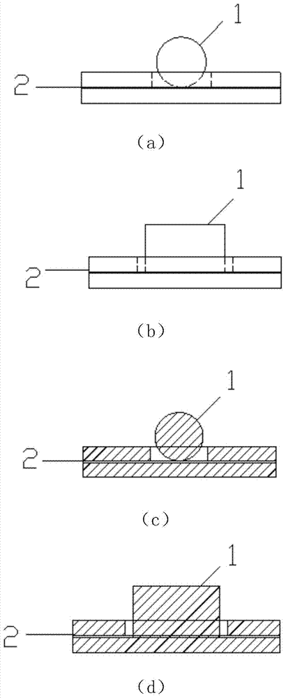
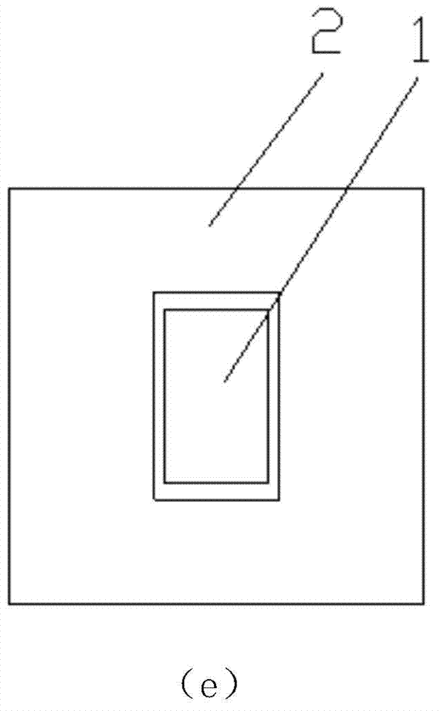
[0032] The loading node includes a rolling column (1) and a backing plate (2), the rolling column (1) is a cylinder, the backing plate (2) is a rectangle, and a rectangular groove is provided in the middle of its upper half, and the length of the rectangular groove is It is longer than the length of the rolling column (1), and its depth is smaller than the radius of the bottom surface of the rolling column (1); the rolling column (1) is placed in the rectangular groove;
[0033] Step 2: Make the loading device.
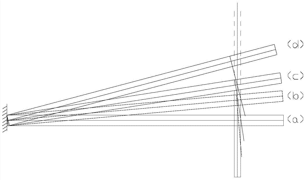
[0034] Such as Figure 7 As shown, the loading device includes a loading node (the loading node includes a rolling column 1 and a backing plate 2), a jacking bracket 3, a load cell 4, a bottom bracket 5 and a hydraulic jack 6; wherein, as Figure 8 As shown, the jacking 3 includes a threaded jack...
PUM
| Property | Measurement | Unit |
|---|---|---|
| Length | aaaaa | aaaaa |
| Width | aaaaa | aaaaa |
| Diameter | aaaaa | aaaaa |
Abstract
Description
Claims
Application Information