
Method for combined inversion of intercept and gradient based on compressional waves and converted shear waves

A technology of converting shear waves and joint inversion, applied in the field of geophysical exploration, can solve the problems of reducing the ambiguity of the inversion process, increasing the stability of the inversion results, and difficult to overcome the instability of the extraction process and the ambiguity of the extraction results. Achieve the effect of reducing multi-solution, reliable method and improving stability

Active Publication Date: 2014-03-26
CHINA UNIV OF PETROLEUM (EAST CHINA)
View PDF5 Cites 13 Cited by
  • Summary
  • Abstract
  • Description
  • Claims
  • Application Information

AI Technical Summary

Problems solved by technology

[0003] However, the traditional method of extracting intercept (P) and gradient (G) only relies on P-wave data, and it is difficult to overcome the instability in the extraction process and the multi-solution of the extraction results; on the other hand, multi-component seismic data records a wealth of The seismic wave field information can make up for the shortcomings of the method of simply using longitudinal waves, reduce the multi-solution nature of the inversion process, increase the stability of the inversion results, and provide a reliable method for oil and gas prediction.

Method used


Image

  • Method for combined inversion of intercept and gradient based on compressional waves and converted shear waves
  • Method for combined inversion of intercept and gradient based on compressional waves and converted shear waves
  • Method for combined inversion of intercept and gradient based on compressional waves and converted shear waves

Examples


Embodiment Construction

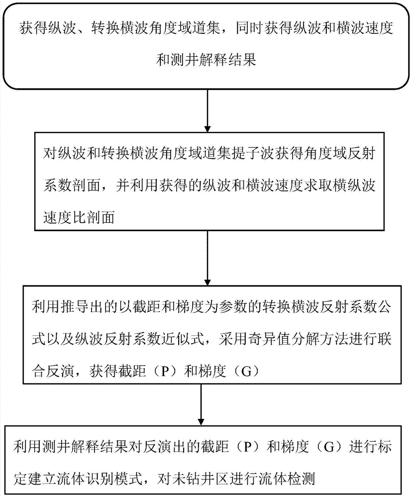
[0026] Such as figure 1 As shown, the method of joint inversion of intercept (P) and gradient (G) based on longitudinal wave and converted shear wave includes the following steps:

[0027] (1) Obtain the longitudinal wave and converted shear wave angle domain gathers, and obtain the longitudinal wave and shear wave velocity and logging interpretation results at the same time; the specific method is as follows:

[0028] Based on the seismic data collected in the field, the seismic imaging method is used to extract the pre-stack seismic angle gather data;

[0029] Obtain compressional and shear wave velocities and logging interpretation results based on field logging data;

[0030] (2) Extract wavelets from the angle domain gathers of longitudinal waves and converted shear waves to obtain the angle domain reflection coefficient profile, and use the obtained longitudinal wave and shear wave velocities to obtain the shear and longitudinal wave velocity ratio profile; the specific...


PUM


Abstract

The invention relates to a method for combined inversion of intercept and gradient based on compressional waves and converted shear waves. The method comprises the following steps of obtaining a compressional wave and converted shear wave angle domain gather, and meanwhile, obtaining the compressional wave and shear wave speeds and well logging interpretation result; extracting the sub-waves from the compressional wave and converted shear wave angle domain gather to obtain an angle domain reflection coefficient profile, and utilizing the obtained compressional wave and shear wave speeds to solve a shear wave and compressional wave ratio profile; utilizing the induced converted shear wave reflection coefficient formula and the compressional wave reflection parameter approximate formula using the intercept and gradient as parameters, and adopting a singular value decomposition method to realize combined inversion so as to obtain the intercept and gradient; utilizing the well logging interpretation result to calibrate the inverted intercept and gradient, establishing a fluid identification mode, and carrying out the fluid detection on the undrilled area. The method has the advantages that the received multi-component earthquake wave field information is sufficiently utilized, the multiple-solution property of the inversion process is reduced, the stability of the inversion process is improved, and a reliable method is provided for the oil and gas prediction.

Description

technical field [0001] The invention belongs to the field of geophysical exploration, and in particular relates to a method for joint inversion of intercept and gradient based on longitudinal waves and converted shear waves. Background technique [0002] Amplitude Versus Offset (Amplitude Versus Offset) is a technique for predicting oil and gas reservoirs by studying the relationship between reflection amplitude and offset to obtain lithological parameters such as velocity and density. Using the Shuey (1985) formula to extract the corresponding intercept (P) and gradient (G) or their combination parameters can effectively carry out oil and gas identification and fluid prediction. Among them, the intercept (P) profile, that is, the vertical incidence reflection coefficient profile, has a high signal-to-noise ratio and resolution, and the vertical incidence and reflection at approximately zero offset will not generate converted shear waves, which can be regarded as the longitu...

Claims


Application Information

Patent Timeline
IPC IPC(8): G01V1/28
Inventor 杜启振陈刚
Owner CHINA UNIV OF PETROLEUM (EAST CHINA)
Learn More