Optical Switch

An optical switch and optical path technology, which is applied in the field of optical switches, can solve the problems of increasing the number of ports, large time and cost, etc., and achieve the effects of suppressing large-scale, suppressing cost increase, and simplifying the number of ports

Inactive Publication Date: 2014-03-26
FURUKAWA ELECTRIC CO LTD
View PDF5 Cites 8 Cited by
  • Summary
  • Abstract
  • Description
  • Claims
  • Application Information

AI Technical Summary

Problems solved by technology

It takes a lot of time and cost to prepare such a special optical part, so it is difficult to

Method used


Image

  • Optical Switch
  • Optical Switch
  • Optical Switch

Examples


Embodiment approach 1

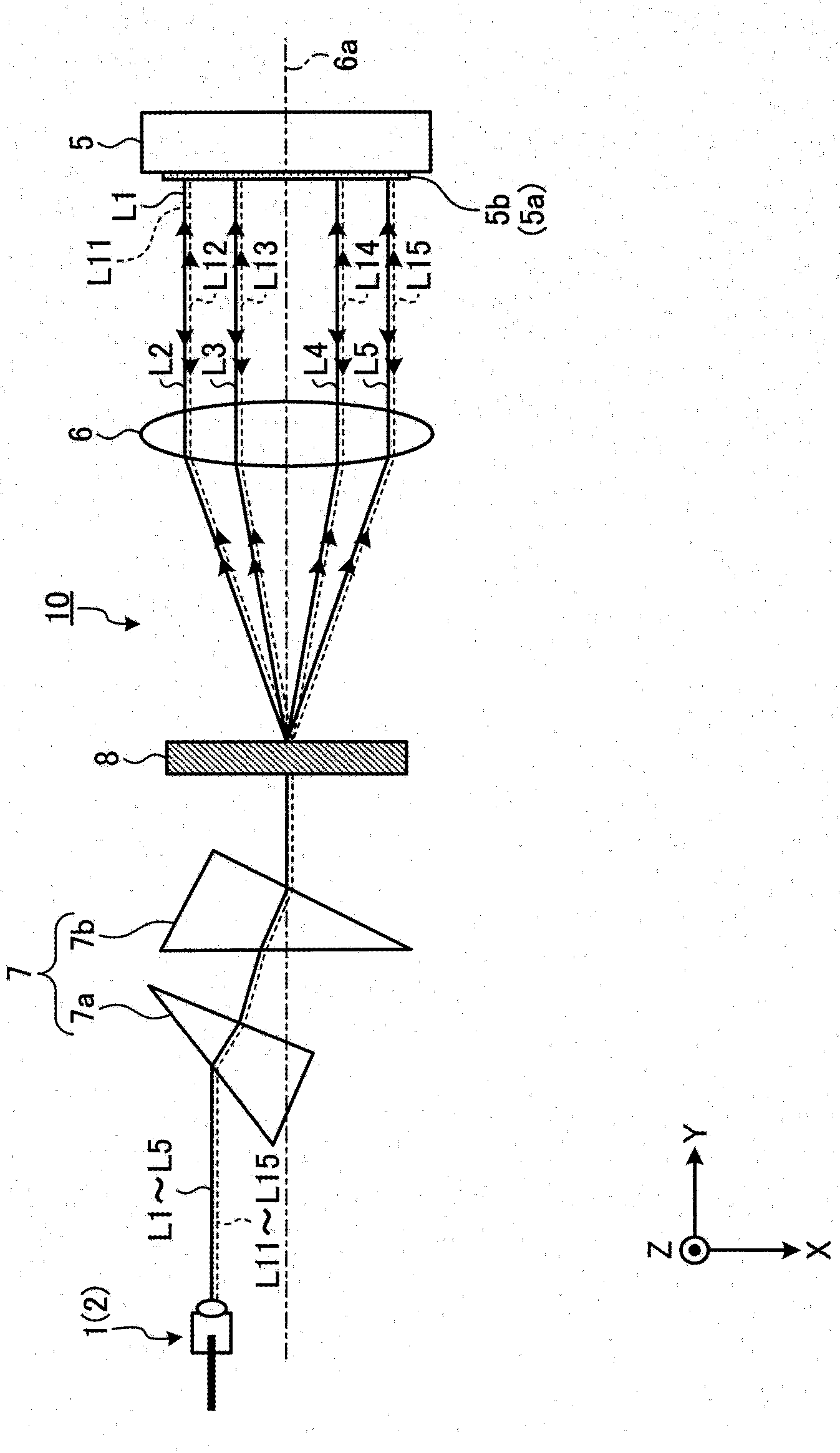
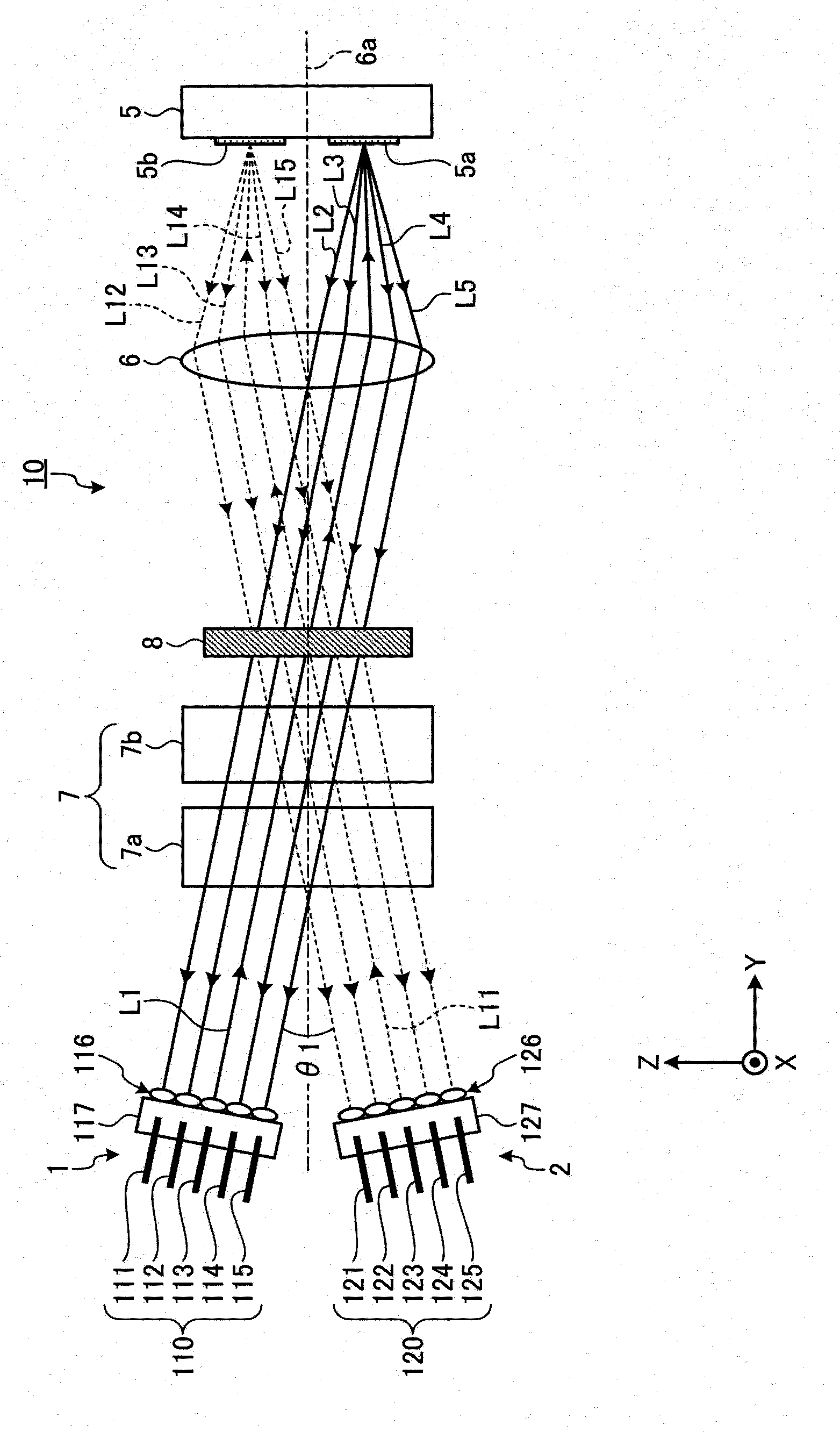
[0069] First, the configuration of the optical switch according to Embodiment 1 of the present invention will be described. figure 1 It is a schematic diagram showing a configuration example of the optical switch according to Embodiment 1 of the present invention. figure 1 In the figure, the optical switch according to the first embodiment is viewed from the Z-axis direction of the XYZ coordinate system. figure 2 It is viewed from the positive direction of the X axis of the XYZ coordinate system figure 1 A diagram of the optical switch is shown. Such as figure 1 , 2 As shown, the optical switch 10 has the following: a plurality of optical input / output ports 1 and 2; an optical path operation unit 5; a condenser lens 6; an anamorphic optical system 7; In addition, since the actual optical paths of the optical switch 10 are greatly bent by the wavelength dispersion element 8, the components from the anamorphic optical system 7 to the optical path operation unit 5 (the anamo...

Embodiment approach 2

[0117] Next, Embodiment 2 of the present invention will be described. In the first embodiment described above, the anamorphic optical system 7 is constituted by a pair of anamorphic prisms 7a and 7b, that is, an anamorphic prism pair. However, in the second embodiment, the anamorphic optical system is constituted by a plurality of cylindrical lenses.

[0118] First, the configuration of an optical switch according to Embodiment 2 of the present invention will be described. Figure 4 It is a schematic diagram showing a configuration example of an optical switch according to Embodiment 2 of the present invention. Figure 4 3 shows the optical switch according to the second embodiment viewed from the Z-axis direction of the XYZ coordinate system. Figure 5 It is viewed from the positive direction of the X axis of the XYZ coordinate system Figure 4 A diagram of the optical switch is shown. Such as Figure 4 , 5 As shown, the optical switch 20 of the second embodiment include...

Embodiment approach 3

[0146] Next, Embodiment 3 of the present invention will be described. In Embodiments 1 and 2 above, the optical input / output ports 1 and 2 are arranged on the same plane parallel to the direction of port arrangement, but in Embodiment 3, the optical ports are arranged on a different plane parallel to the direction of port arrangement. Input / Output Port 1, 2.

[0147] Figure 6 It is a schematic diagram showing a configuration example of an optical switch according to Embodiment 3 of the present invention. Figure 6 The figure in the figure looks at the optical switch of the third embodiment from the Z-axis direction of the XYZ coordinate system. Figure 7 It is viewed from the positive direction of the X axis of the XYZ coordinate system Figure 6 A diagram of the optical switch is shown. Such as Figure 6 , 7 As shown, the optical input / output ports 1 and 2 of the optical switch 30 according to Embodiment 3 are arranged in two rows along the port arrangement direction (...


PUM


Abstract

The invention provides an optical switch which is small in size, low in cost and large in number of light input/output ports. An optical switch (10) includes light input/output ports (1,2), each having a port group (110,120) of inputting/outputting a light, an optical path manipulation unit (5) having optical path switching units (5a,5b,5c) of switching an optical path of a light from an input port in the port group to an optical path toward an output port in the same port group according to each of the light input/output ports, and a condenser lens (6) condensing light from the light input/output ports on the optical path switching units corresponding to the port groups and optically-couples the light input/output ports with the optical path manipulation unit. The input/output optical paths of the light input/output ports with respect to the condenser lens are parallel to each other between the ports in the same port group and are unparallel to each other between the ports in the different port groups as seen from a direction perpendicular to a port arrangement direction.

Description

technical field [0001] The present invention relates to optical switches. Background technique [0002] Conventionally, in an optical transmission system, an optical switch is used to switch the optical path of signal light. In such an optical switch, as an optical path conversion unit for switching the optical path of signal light, a mirror (hereinafter referred to as MEMS mirror) or LCOS (Micro Electro Mechanical Systems) technology using MEMS (Micro Electro Mechanical Systems) technology is generally provided Liquid crystal silicon: Liquid Crystal On Silicon). The MEMS mirror is rotatably supported around a predetermined rotation axis, and its rotation angle is adjusted via a drive mechanism. An optical switch equipped with a MEMS reflector reflects signal light incident from a certain optical path by the MEMS reflector, and outputs the reflected signal light along a specific optical path, thereby realizing an optical switch operation. On the other hand, LCOS is a spat...

Claims


Application Information

Patent Timeline
IPC IPC(8): G02B6/35G02B6/32
CPCG02B6/3512G02B6/3556G02B6/356G02B6/29311H04Q11/0005
Inventor 岩间真木加木信行小栗淳司
Owner FURUKAWA ELECTRIC CO LTD
Why Eureka
Try Eureka