Transformer rack

A technology for transformers and benches, applied in the directions of transformer/reactor installation/support/suspension, substations mounted on columns, etc., can solve the problems of unstable installation, corrosion, high cost, etc. The effect of the connection area

Inactive Publication Date: 2014-03-26
CHONGQING JUKANG BUILDING MATERIAL
View PDF0 Cites 4 Cited by
  • Summary
  • Abstract
  • Description
  • Claims
  • Application Information

AI Technical Summary

Problems solved by technology

[0003] Most of the existing transformer stands are planar frames, and the two ends of the steel frame are provided with hoops connected with the poles. It takes a lot of time to adjust the center of gravity of the transformer in the plane formed by the two vertical poles. Once the installation is deviated, the transformer stand will be subject to additional torque, resulting in unstable installation; in addition, due to the harsh environment of the transformer stand, Corrosion is easily caused by wind and sun; both of the above two points seriously affect the reliability and safety of transformer operation

Method used


Image

  • Transformer rack

Examples


Embodiment Construction

[0010] Below in conjunction with accompanying drawing and embodiment the technical solution of the present invention is further described:

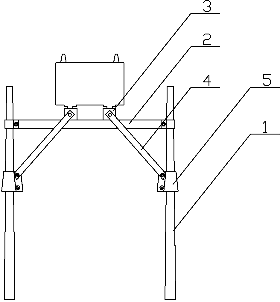
[0011] Such as figure 1 The present invention as shown provides a kind of transformer stand, comprises the crossbeam 2 that has hoop that connects two upright poles 1, a pair of parallel girders 3 that are fixed on the top of crossbeam 2 by bolts, and the ends of parallel girders 3 Hinged oblique support steel beam 4, the other end of the oblique support steel beam 4 is fixed on the vertical pole 1 through the lower hoop 5, the lower hoop 5 is in the shape of a cone, and its fastening screws are at least two upper and lower, the cone The lower hoop 5 of the shape can increase the connection area between the hoop and the vertical bar 1, and can form a wedge-shaped connection with the vertical bar 1 at the same time, so the stability of the obliquely supported steel beam 4 can be guaranteed. In order to ensure the overall resistance of the ...


PUM


Abstract

The invention relates to a power transmission and transformation device, in particular to a transformer rack. The transformer rack comprises a cross beam, a pair of parallel longitudinal beams and diagonal supporting steel beams, wherein two vertical rods are connected through the cross beam, the cross beam is provided with hoop rings, the parallel longitudinal beams are fixed to the top of the cross beam through bolts, and the diagonal supporting steel beams are hinged to the ends of the parallel longitudinal beams. The other end of each diagonal supporting steel beam is fixed to one vertical rod through a lower hoop ring, wherein the lower hoop ring is of a conical cylinder shape, and the lower hoop ring at least comprises an upper fastening screw and a lower fastening screw. By the adoption of the transformer rack, a transformer can be installed stably, shaking of the transformer is prevented, and the corrosion resistance performance is good.

Description

technical field [0001] The invention relates to a power transmission and transformation device; in particular, it relates to a transformer stand. Background technique [0002] The transformer stand is a kind of support for overhead installation of transformers, usually set between two poles, the structure of the transformer stand itself has a major impact on the firm installation of the transformer, and is related to the long-term stable operation of the transformer. [0003] Most of the existing transformer stands are planar frames, and the two ends of the steel frame are provided with hoops connected with the poles. It takes a lot of time to adjust the center of gravity of the transformer in the plane formed by the two vertical poles. Once the installation is deviated, the transformer stand will be subject to additional torque, resulting in unstable installation; in addition, due to the harsh environment of the transformer stand, Corrosion is very easy to occur in wind a...

Claims


Application Information

Patent Timeline
Patent Type & Authority Applications(China)
IPC IPC(8): H01F27/06H02B5/02
Inventor 周炫张信聪
Owner CHONGQING JUKANG BUILDING MATERIAL
Why Eureka
Try Eureka