Handheld electronic device

A technology of electronic devices and bodies, applied in the direction of antenna supports/mounting devices, circuits, electrical components, etc., can solve the problem of not being shielded by radiation effects, and achieve the effect of maintaining integrity

Active Publication Date: 2014-03-26
ACER INC
View PDF7 Cites 5 Cited by
  • Summary
  • Abstract
  • Description
  • Claims
  • Application Information

AI Technical Summary

Problems solved by technology

In order to solve such a problem, an antenna window (Antenna Window) must be opened on the metal shell so that the antenna can successfully send and receive signals, so that the radiation effect is not shielded

Method used


Image

  • Handheld electronic device
  • Handheld electronic device
  • Handheld electronic device

Examples


Embodiment Construction

[0036] In order to comply with the current design trend of thinner and lighter handheld electronic devices while maintaining the performance of the antenna, the present invention provides an antenna formed by using a heat dissipation vent structure. Since the cooling vent is an indispensable structure for the original design of the handheld electronic device, such a setting will not affect the integrity of the design of the handheld electronic device.

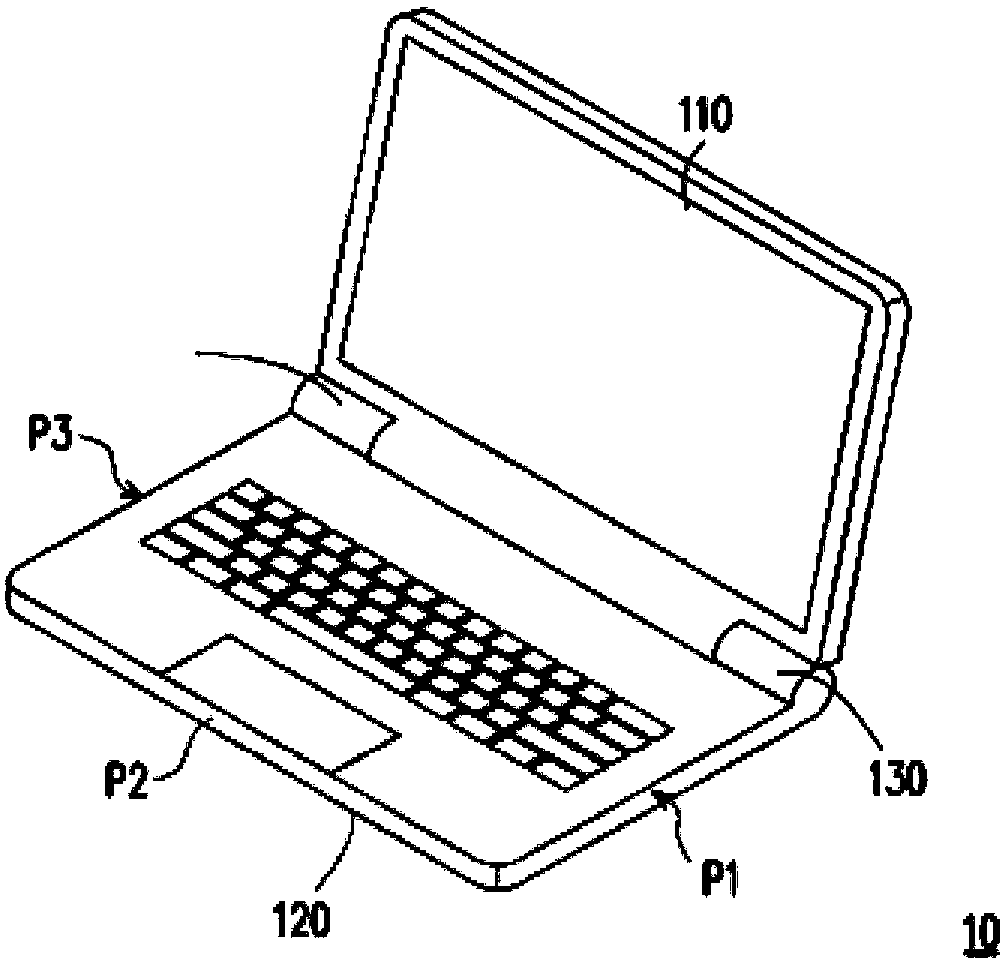
[0037] figure 1 It is a schematic diagram of the appearance of a handheld electronic device according to an embodiment of the present invention. In this embodiment, the handheld electronic device is a notebook computer, but the present invention is not limited thereto. For example, any handheld electronic device with the antenna disposed on the heat dissipation vent structure falls within the scope of the present invention. Please refer to figure 1 , the handheld electronic device 10 includes a first body 110 and a second bod...


PUM


Abstract

The invention provides a handheld electronic device. The handheld electronic device comprises a body, a heat dissipation air opening structure and an antenna, wherein the heat dissipation air opening structure is arranged on the body; the antenna is arranged on the heat dissipation air opening structure and used for receiving and sending at least a radio-frequency signal.

Description

technical field [0001] The invention relates to a hand-held electronic device, in particular to a hand-held electronic device in which an antenna is arranged on a cooling air outlet structure. Background technique [0002] With the evolution of the times and the development of technology, current handheld electronic devices, whether they are notebook computers or tablet computers (Tablet), are all designed towards lighter and thinner. The metal shell is also one of the frequently used materials, which makes the handheld electronic device more textured while keeping it thin and light. However, the use of a metal shell will also make the design threshold more stringently challenged. The first part to bear the brunt is the key parts such as the antenna. [0003] Good antenna radiation characteristics are often directly related to the quality of receiving signals. A good antenna needs a good environment, but the existing thin and light-oriented handheld electronic device prod...

Claims


Application Information

Patent Timeline
IPC IPC(8): H01Q1/22H01Q1/36H01Q5/00H01Q5/35
Inventor 林敬基
Owner ACER INC
Why Eureka
Try Eureka