Power control method of battery management system

A battery management system and power control technology, applied in battery circuit devices, current collectors, electric vehicles, etc., can solve problems such as affecting the control of the whole vehicle, limiting power, and short mileage, improving comfort, preventing sudden changes, and being flexible. high sex effect

Active Publication Date: 2014-03-26
HUIZHOU EPOWER ELECTRONICS
View PDF3 Cites 43 Cited by
  • Summary
  • Abstract
  • Description
  • Claims
  • Application Information

AI Technical Summary

Problems solved by technology

Power control affects the driving performance. If the control is not good, people will feel that the vehicle is underpowered, driving will feel frustrated, and the mileage will be short, etc.
From the perspective of the battery factory, it is also hoped to control the battery power well. Under different voltage, current, and temperature conditions, the allowable charging and discharging power of the battery needs to be adjusted reasonably, otherwise the battery will be overcharged or overdischarged, affecting battery life
[0003] The current power control strategy is mainly based on the look-up table control of battery temperature and SOC. Basically, it is controlled in sections. The problem brought by the section control is that the power change is not continuous, and there may even be a large jump at the section point. change, affecting the control of the vehicle
Another problem with power control is that power needs to be limited when there is a battery undervoltage fault. The key lies in how much undervoltage needs to be limited, how much to limit, and how to gradually change to the limit value. There is no systematic conclusion yet.

Method used


Image

  • Power control method of battery management system
  • Power control method of battery management system
  • Power control method of battery management system

Examples


Embodiment Construction

[0032] In order to allow those skilled in the art to better understand the technical solutions of the present invention, the present invention will be further described below in conjunction with the accompanying drawings.

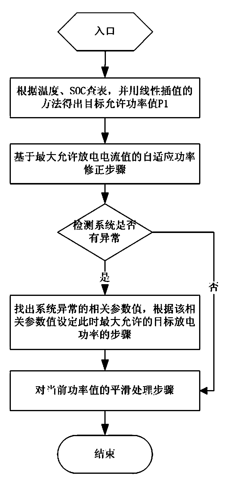
[0033] The specific embodiment of the present invention is as Figure 1 ~ Figure 4 As shown, a power control method of a battery management system, the method includes

[0034] S1: Establish a two-dimensional power table of the maximum allowable discharge power, temperature, and SOC.

[0035] Among them, the table is obtained by the battery manufacturer according to the characteristics test of the new battery when the battery is produced.

[0036] S2: Detect the temperature and SOC value of the battery pack in the current working state, and obtain the allowable power value according to the actual temperature and SOC look-up table and linear interpolation method.

[0037] First judge the temperature interval, determine the power division interval correspon...


PUM


Abstract

The invention relates to a power control method of a battery management system. The power control method includes the following steps: establishing a two-dimensional power list of temperature and SOC (state of charge); detecting current temperature and an SOC value, looking up the list and estimating a current maximum allowable discharging power value according to a linear interpolation method; performing self-adaptive power correction; if abnormity of the system is detected, finding out related parameter values of abnormity of the system, and setting maximum allowable target discharging power at the time according to the related parameter values; smoothing the power value; transmitting the set maximum allowable target discharging power to a whole vehicle controller, and performing corresponding control by the whole vehicle controller. Compared with the prior art, the power control method has the advantages that the method can automatically adapt to environment and changing of circumstances of declination of actual battery capacity or increase of internal battery resistance and the like to correct allowable power values, and flexibility is high; smoothing is adopted, so that abrupt changing of the power value can be effectively prevented, influence caused by abrupt changing can be reduced, and comfortableness in the process of driving can be improved.

Description

technical field [0001] The invention relates to a power control method, in particular to a power control method of a battery management system. Background technique [0002] With the development of electric vehicles, both vehicle manufacturers and battery manufacturers have put forward requirements for power control. Vehicle manufacturers hope to refine the battery power control strategy in consideration of vehicle operation stability, safety, and reliability. Power control affects the driving performance. If the control is not good, people will feel that the vehicle is underpowered, driving will feel frustrated, and the driving mileage will be short. From the perspective of the battery factory, it is also hoped to control the battery power well. Under different voltage, current, and temperature conditions, the allowable charging and discharging power of the battery needs to be adjusted reasonably, otherwise the battery will be overcharged or overdischarged, affecting batt...

Claims


Application Information

Patent Timeline
Patent Type & Authority Applications(China)
IPC IPC(8): H02J7/00
Inventor 刘飞文锋阮旭松樊耀国
Owner HUIZHOU EPOWER ELECTRONICS
Why Eureka
Try Eureka