Wireless charge system

A wireless charging and charging system technology, applied in electromagnetic wave systems, current collectors, electric vehicles, etc., can solve problems such as alignment, poor transmission efficiency, and insufficient coupling area

Inactive Publication Date: 2014-03-26
WISTRON CORP
View PDF4 Cites 11 Cited by
  • Summary
  • Abstract
  • Description
  • Claims
  • Application Information

AI Technical Summary

Problems solved by technology

However, when the receiver is placed on the transmitter for charging, it is often impossible to accurately align the coils of the two, resulting in poor transmission efficiency, prolonging the charging time and wasting power. When the efficiency is too low, the system may even will directly short circuit without action
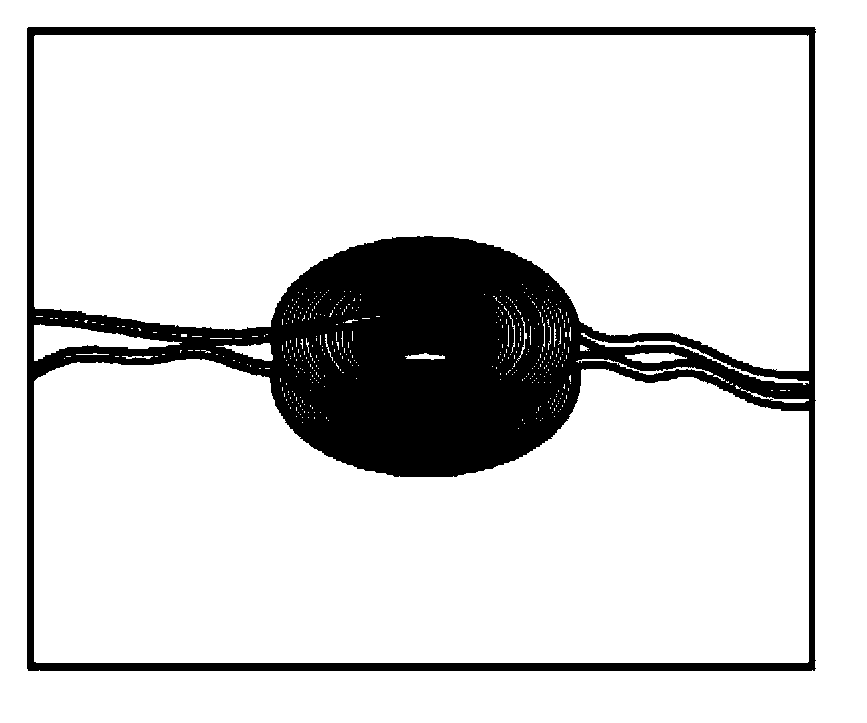
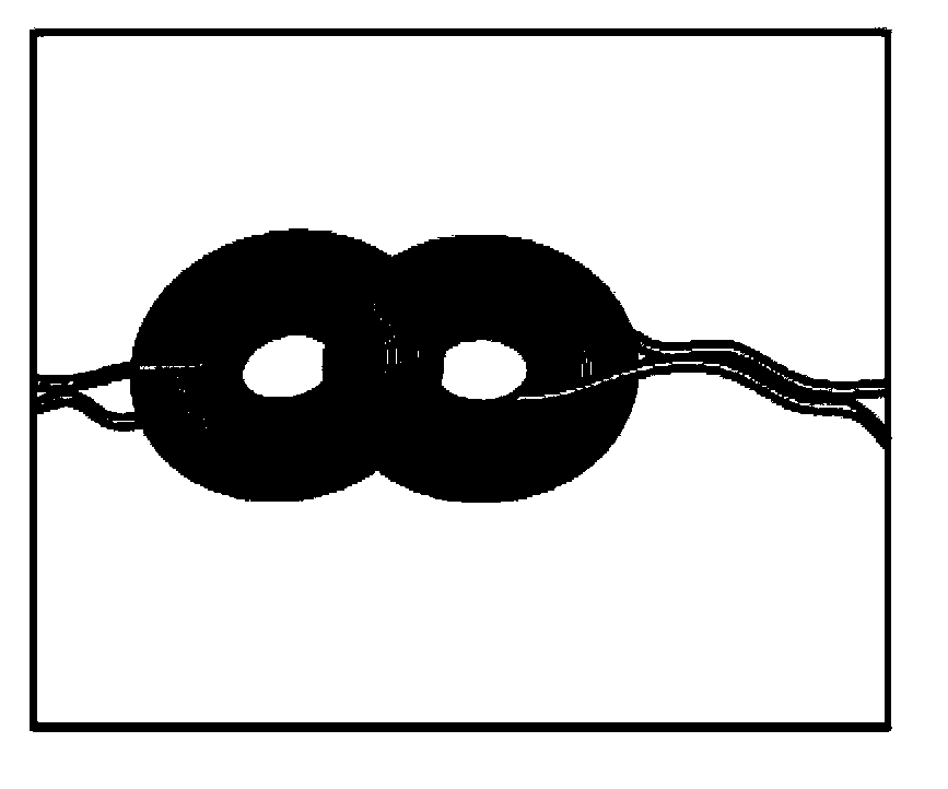
[0003] like Figure 1A , Figure 1B as shown, Figure 1A It shows the situation where the two coils for electromagnetic induction are aligned in the horizontal direction. At this time, the coupling area is large and the transmission efficiency is the best. Figure 1B It shows that the two coils are offset in the horizontal direction. At this time, the insufficient coupling area leads to a decrease in transmission efficiency.
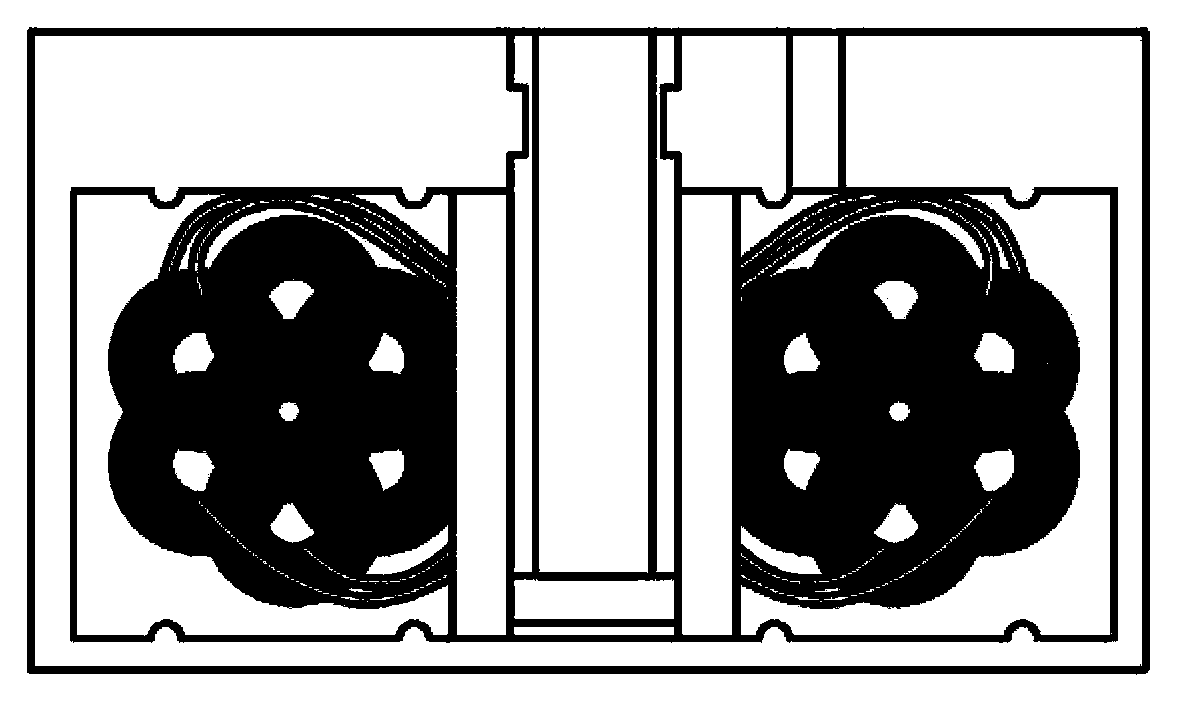
Among the current products, the coil of the transmitter is directly fixed on the lower cover of the housing, which makes assembly easy, and because the user cannot accurately align the two coils when placing the receiver, so if figure 2 As shown, usually multiple sending coils are set on the transmitter side to form a coil array, which makes the placement of the receiver more flexible
But such setting will increase redundant power consumption, not economical and energy-saving

Method used


Image

  • Wireless charge system
  • Wireless charge system
  • Wireless charge system

Examples


Embodiment Construction

[0030] image 3 It is a schematic diagram of a wireless charging system according to an embodiment of the present invention. Such as image 3 As shown, the wireless charging system of the present invention includes a charging transmitter 10 and a charging receiver 20 . When charging, the charging receiver 20 to be charged will be placed on the surface of the platform on the charging transmitter 10 that provides power, and there will be no connection between the two through any physical wire, so it is called wireless charging.

[0031] Figure 4 It is an exploded perspective view of a charging transmitter according to an embodiment of the present invention. The charging transmitter 10 is mainly composed of an upper cover 11 , a lower cover 12 , a transmitting coil 13 , a circuit board 14 , a magnet 15 , and a ball 16 .

[0032] The upper cover 11 and the lower cover 12 are the upper and lower casings of the charging transmitter 10 respectively. The surface of the upper cov...


PUM


Abstract

The invention provides a wireless charge system, comprising a charge receiver and a charge transmitter. The charge receiver comprises a reception coil used for receiving electric power and a first magnet used for carrying the reception coil. The charge transmitter comprises a transmission coil used for transmitting electric power and a second magnet used for carrying the transmission coil and capable of moving inside the charge transmitter. The second magnet is attracted by the first magnet to move to an alignment position, thereby enabling the transmission coil and the reception coil to be aligned.

Description

technical field [0001] The present invention relates to a wireless charging system, and in particular to a wireless charging system in which a sending coil and a receiving coil can be automatically guided to an alignment position. Background technique [0002] Wireless charging technology mainly transmits power through the electromagnetic induction coil of the transmitter and receiver, so there is no need to use physical wiring connections. However, when the receiver is placed on the transmitter for charging, it is often impossible to accurately align the coils of the two, resulting in poor transmission efficiency, prolonging the charging time and wasting power. When the efficiency is too low, the system may even It will directly short circuit without action. [0003] Such as Figure 1A , Figure 1B as shown, Figure 1A It shows the situation where the two coils for electromagnetic induction are aligned in the horizontal direction. At this time, the coupling area is large ...

Claims


Application Information

Patent Timeline
Patent Type & Authority Applications(China)
IPC IPC(8): H02J17/00H02J7/00H02J50/10
Inventor 李尚懋高山宝庄政祥
Owner WISTRON CORP
Why Eureka
Try Eureka