
Dynamic token with key protection function and working method thereof

A technology of dynamic token and protection function, applied in the field of keys, can solve problems such as affecting the service life of electronic products

Active Publication Date: 2014-03-26
FEITIAN TECHNOLOGIES
View PDF4 Cites 3 Cited by
  • Summary
  • Abstract
  • Description
  • Claims
  • Application Information

AI Technical Summary

Problems solved by technology

[0004] In life, we often encounter situations like this: when users place electronic products with hard objects (such as keys, etc.), it will cause unnecessary button power consumption when the buttons of electronic products are pressed by hard objects, especially for Some products that require high battery power consumption (such as dynamic tokens, etc.), this phenomenon seriously affects the service life of electronic products

Method used


Image

  • Dynamic token with key protection function and working method thereof
  • Dynamic token with key protection function and working method thereof
  • Dynamic token with key protection function and working method thereof

Examples


Embodiment 1

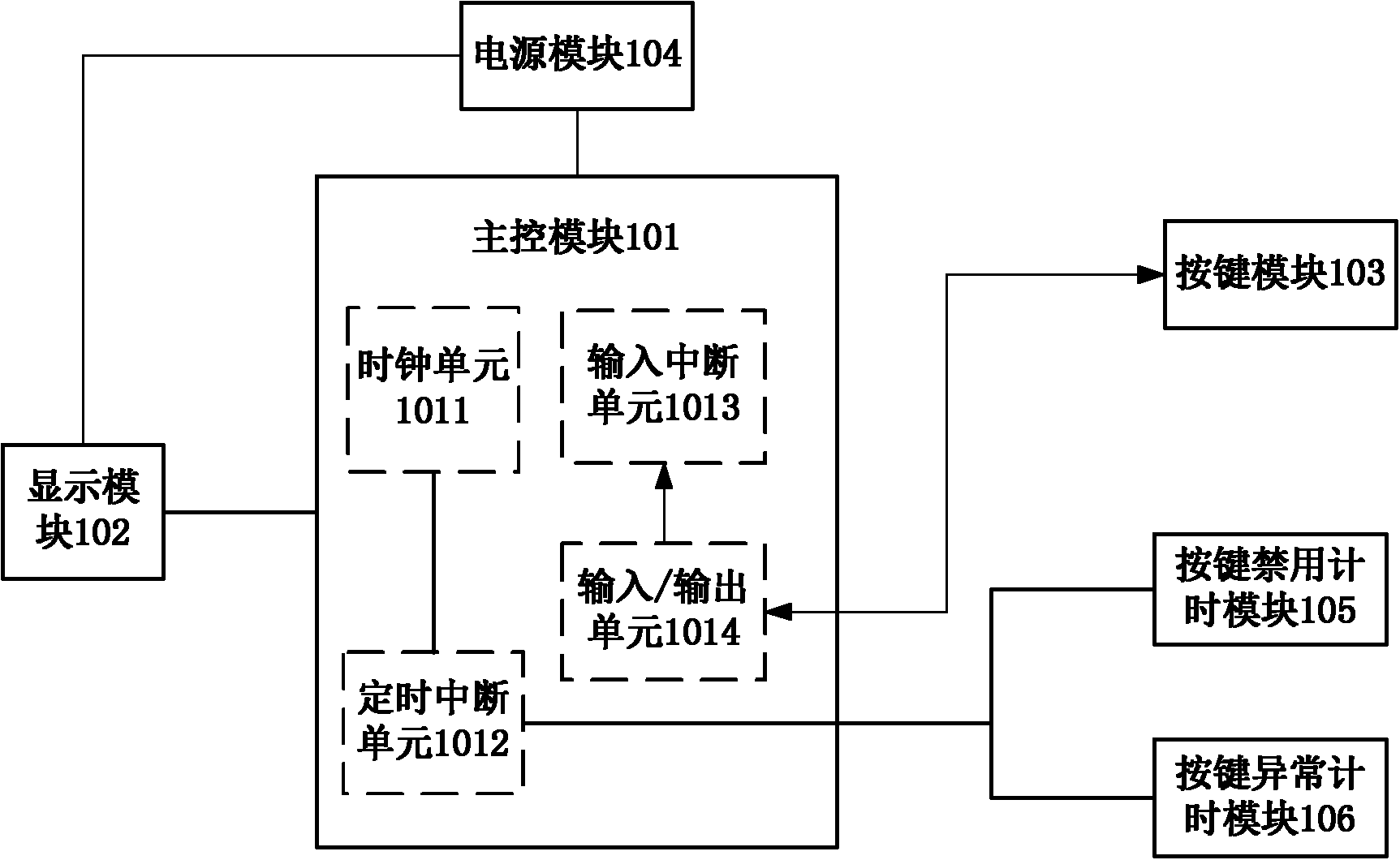
[0091] Embodiment 1 of the present invention provides a dynamic token with a key protection function, such as figure 1 As shown, it includes: a main control module 101, a display module 102, a key module 103, a power supply module 104, a key disable timing module 105 and a key abnormal timing module 106; wherein, the main control module 101 includes a clock unit 1011, a timing interrupt unit 1012, an input interrupt unit 1013 and an input / output unit 1014;

[0092] The main control module 101: connected with the input / output unit, used for controlling the output level of the input / output unit 1014; connected with the input interrupt unit, used for inputting the input / output unit 1014 When the preset level changes, the input interrupt unit 1013 is controlled to generate an input interrupt; it is connected to the clock unit and the timing interrupt unit, and is used to control the timing interrupt unit 1012 to generate an input interrupt triggered by the clock unit 1011 timed i...

Embodiment 2

[0130] Embodiment 2 of the present invention provides a working method of a dynamic token with key protection function on the basis of Embodiment 1, such as Image 6 shown, including:

[0131] Step 201: The dynamic token is powered on and initialized, the initial state of the input pin of the input / output unit is set as the first level, and the output pin of the input / output unit is initialized to the second level;

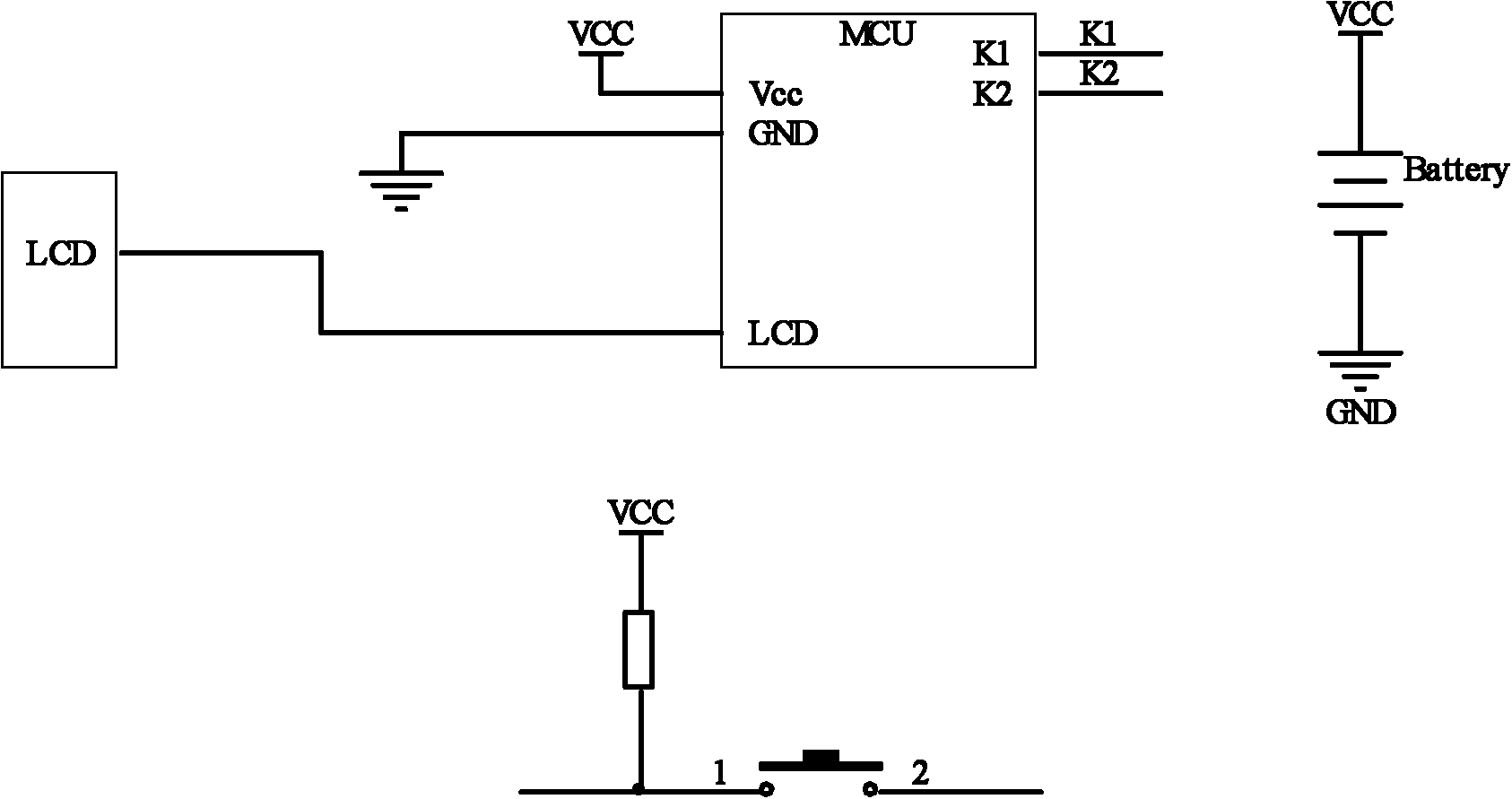
[0132] Among them, in embodiment 1 figure 2 , the initial state of the input pin of the input / output unit is taken as the first level, and the output pin of the input / output unit is initialized to the second level, specifically: the key in the key module ( Pin 1 of Key1) is connected to VCC through a resistor (R1), then the initial state of the input pin (K1) in the input / output unit is high level, and the output pin (K2) is initialized to low power flat;

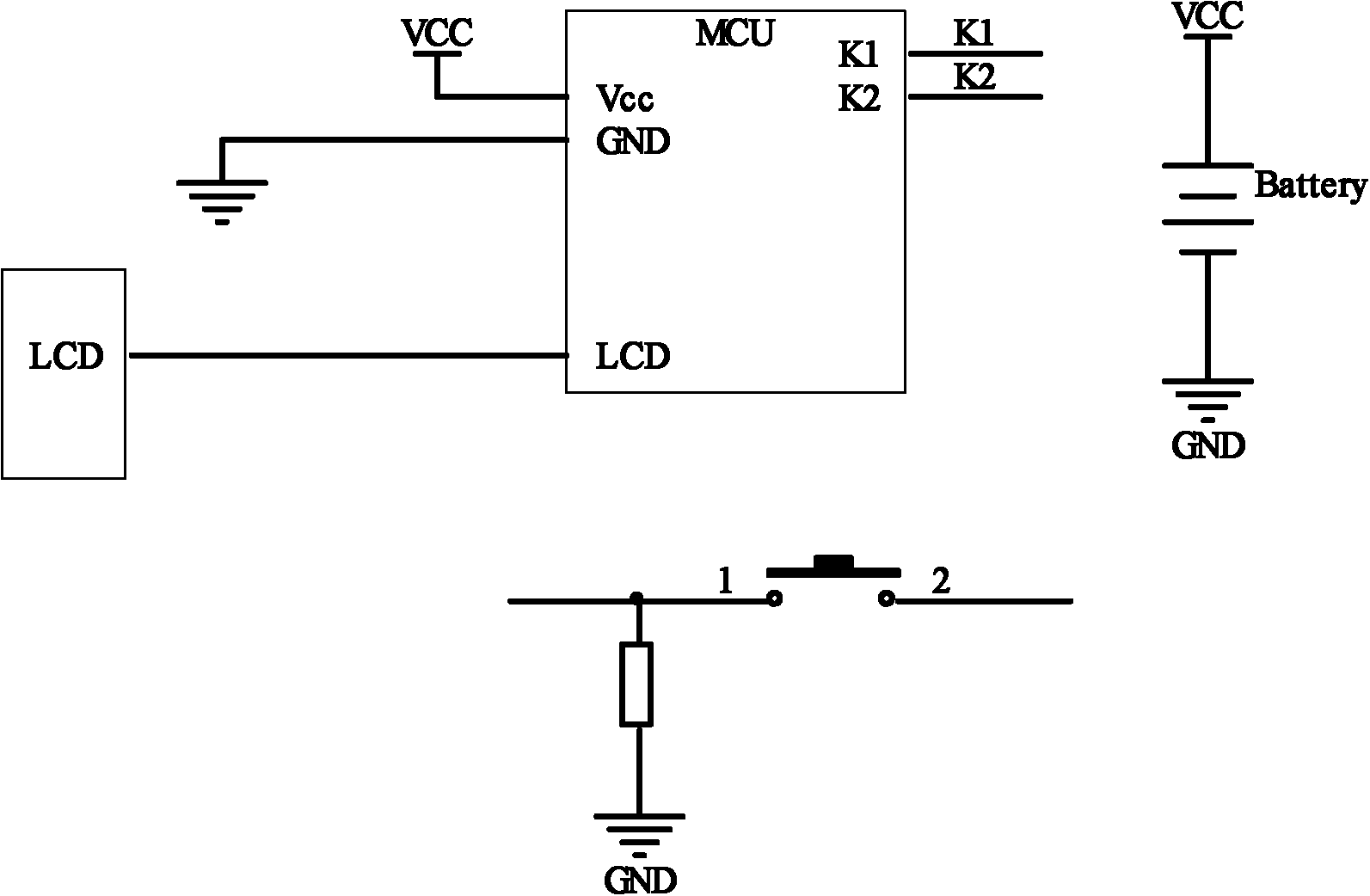
[0133] Among them, in embodiment 1 image 3 , the initial state of the input pin of the input / output un...


PUM


Abstract

The invention discloses a dynamic token with the key protection function and a working method of the dynamic token and belongs to the technical field of keys. The dynamic token comprises a master control module, a key module, a key forbidden timing module and a key abnormity timing module, wherein the master control module comprises a clock unit, a timing interrupt unit, an input interrupt unit and an input / output unit. The working method includes the steps that when the dynamic token detects that input interrupt happens to the input interrupt unit, the dynamic token is awakened, and input awakening identification is set; when the dynamic token detects that timing interrupt happens to the timing interrupt unit, the dynamic token is awakened, and timing awakening identification is set; if key awakening identification is set, key operation is executed, and if the timing awakening identification is set, the key protection procedure is executed. Through the technical scheme, power consumption caused by abnormal key operation on the dynamic token can be reduced, and the service life of the dynamic token is prolonged.

Description

technical field [0001] The invention relates to the field of button technology, in particular to a dynamic token with a button protection function and a working method thereof. Background technique [0002] A dynamic token is a terminal used to generate a dynamic password. The dynamic password can be used to confirm the legal identity of the user, thereby ensuring the security of the user's business access on the basis of the user logging in with a legal identity. Dynamic password authentication technology is considered to be one of the most effective solutions to user authentication at present, and thus is widely used in various information system scenarios such as banking, securities, third-party payment, and large enterprises. [0003] With the popularity of electronic products, the power consumption of buttons has become a topic that more and more manufacturers are scrambling to pay attention to. The length of use of electronic products directly affects the performance o...

Claims


Application Information

Patent Timeline
Patent Type & Authority Applications(China)
IPC IPC(8): H04L9/32G06F1/32G06F3/02G06F13/24
CPCY02D10/00
Inventor 陆舟于华章
Owner FEITIAN TECHNOLOGIES
Learn More