
Image capture system and imaging optical system

An image capture and imaging system technology, applied in the field of image capture systems, can solve problems such as the movement of imaging components

Active Publication Date: 2014-03-26
RICOH KK
View PDF8 Cites 25 Cited by
  • Summary
  • Abstract
  • Description
  • Claims
  • Application Information

AI Technical Summary

Problems solved by technology

This causes the imaging element to move substantially

Method used


Image

  • Image capture system and imaging optical system
  • Image capture system and imaging optical system
  • Image capture system and imaging optical system

Examples


Embodiment Construction

[0033] An embodiment will be described below.

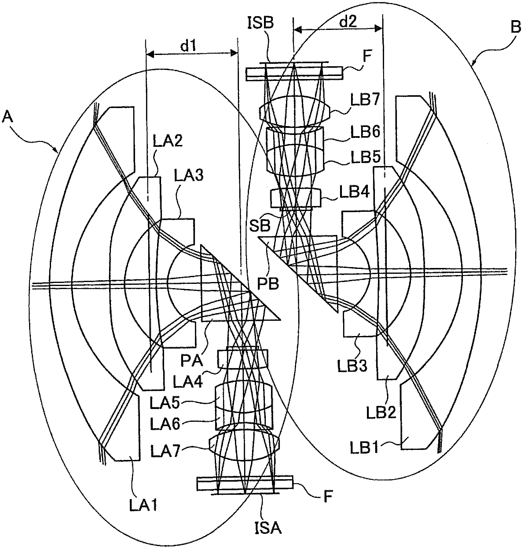
[0034] figure 1 An example of two imaging systems making up one image capture system is shown.

[0035] In other words, the two imaging systems constituting the image capturing system are imaging system A and imaging system B shown in the figure. The imaging systems A and B have the same structure.

[0036] Each of the imaging systems A, B has "a wide-angle lens having an angle of view greater than 180 degrees and an imaging sensor that captures an image formed by the wide-angle lens".

[0037] This imaging sensor is a "two-dimensional solid-state imaging element".

[0038] The wide-angle lens of the imaging system A includes a front mirror group, a reflective surface and a rear mirror group.

[0039] The "front group" consists of lenses LA1 to LA3, and the "rear group" consists of lenses LA4 to LA7. The reference numeral PA denotes "rectangular prism".

[0040] The aperture stop SA is provided on the object side of the len...


PUM


Abstract

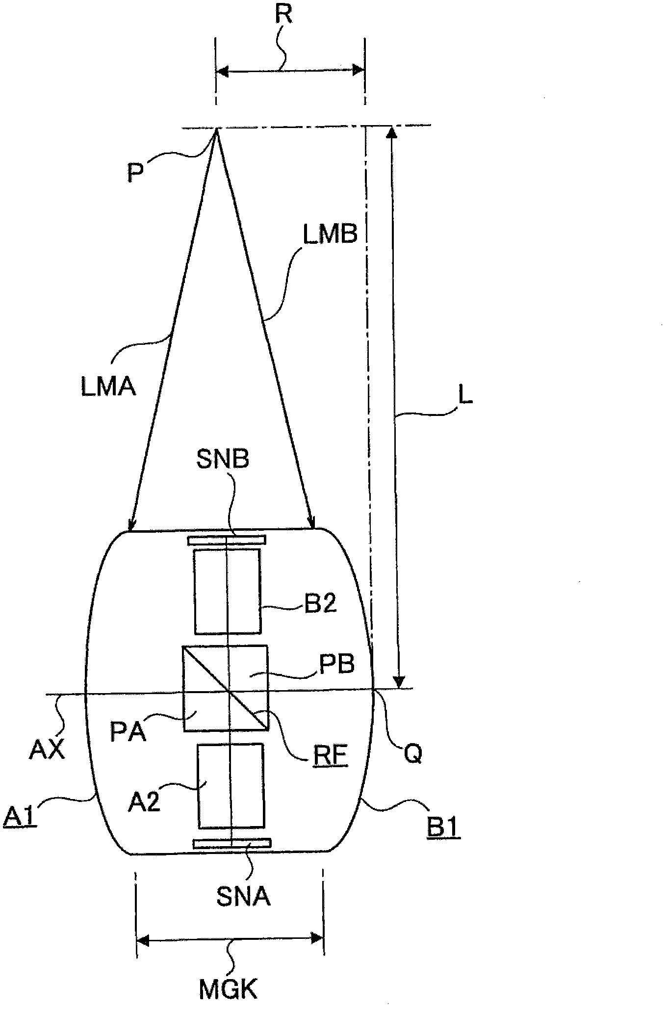
An image capture system including two imaging systems of the same structure each having a wide-angle lens, which includes a front group, a reflection surface, and a rear group arranged in order from an object side, has a field angle larger than 180 degrees, and bends an optical axis of the front group toward the rear group by the reflection surface, and an imaging sensor, obtains an image in a solid angle of 4pi radian by combining images imaged by the imaging systems. Each of the two wide-angle lenses includes the reflection surface between the front group and the rear group, the reflection surfaces are made to be common to the two imaging systems. This reduces an interval between lenses nearest to the object side in the front groups of the two wide-angle lenses, thereby reducing a distance between maximum field angles of the two wide-angle lenses.

Description

technical field [0001] The present invention relates to image capture systems and in particular omnidirectional image capture systems, and imaging optics. Background technique [0002] As an image capture system that captures images omnidirectionally at the same time, there is known one that uses two wide-angle lenses (refer to Japanese Patent Application Laid-Open No. 2010-271675 and Japanese Patent No. 3290993). [0003] This omnidirectional image capture system can simultaneously acquire image information in all directions (with a solid angle of 4π radians), and thus can be effectively used in security surveillance cameras, vehicle cameras or the like. [0004] For example, in news reporting or similar fields, it is necessary to record high-precision, high-quality image information in "hand-held conditions" using a small-sized omni-directional image capture system. [0005] An omnidirectional image of weather conditions can be captured and used to analyze weather informa...

Claims


Application Information

Patent Timeline
Patent Type & Authority Applications(China)
IPC IPC(8): H04N5/225G02B13/06G03B17/17
CPCG03B17/17G02B13/0065G02B17/08G02B13/06G03B37/04H04N23/45H04N23/698G02B9/62
Inventor 佐藤裕之寺尾典之入野祥明田中智宪今江望原田亨竹中博一山本英明增田宪介泽口聪别所大介庄原诚伊藤洋一高巢修作
Owner RICOH KK
Learn More