Nasal irrigator built in nasal vestibule

A nasal irrigation, built-in technology, applied in the fields of personal medical care and sanitary appliances, can solve problems such as increasing infection

Inactive Publication Date: 2014-04-02
黄海兵
View PDF9 Cites 0 Cited by
  • Summary
  • Abstract
  • Description
  • Claims
  • Application Information

AI Technical Summary

Problems solved by technology

The maximum diameter of the nozzle of the existing general-purpose nasal cavity irrigator is basically designed to be larger than the aperture of the anterior pore of the normal population, in order to achieve the purpose of lavaging the nasal cavity after the irrigating fluid enters the nasal cavity on one side; but the rinsing fluid enters the nasal cavity The nasal vestibule between the anterior nostril and the inner nostril first flows through the nose, where a large amount of solid particles and pathogenic bacteria are accumulated daily, so such pathogenic substances will be washed with the nozzle of the traditional nasal irrigator. A large amount of irrigation fluid entering the nasal cavity increases the possibility of infection

Method used


Image

  • Nasal irrigator built in nasal vestibule
  • Nasal irrigator built in nasal vestibule
  • Nasal irrigator built in nasal vestibule

Examples


Embodiment Construction

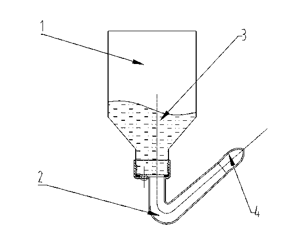
[0016] Such as figure 1 As shown, a soft nozzle nasal vestibule built-in nasal cavity irrigator includes a liquid storage container 1, which contains a flushing liquid 3, and the two ends of the infusion tube 2 are respectively connected to the liquid storage container 1 and the soft nozzle 4.

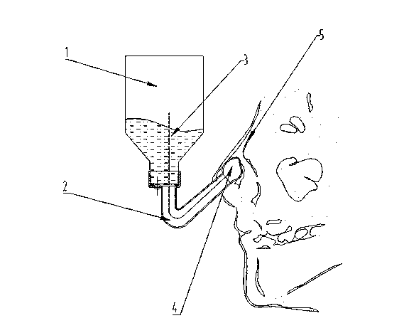
[0017] Such as figure 2 Shown, during use, now the soft nozzle 4 in a kind of soft nozzle nasal vestibule built-in nasal cavity irrigator that rinse liquid 3 is housed is put into the nasal vestibule 5 positions in the nasal cavity.

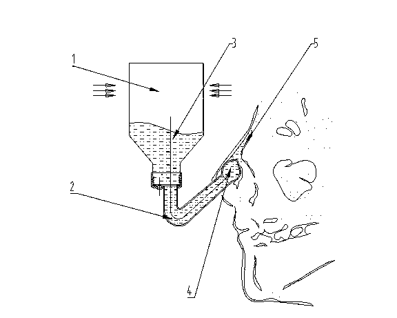
[0018] Such as image 3 As shown, pressure is applied to the liquid storage container 1 containing the irrigating liquid 3, so that the irrigating liquid 3 is sprayed out from the soft nozzle 4 through the infusion tube 2 to rinse the affected part.


PUM


Abstract

The invention discloses a nasal irrigator built in nasal vestibule. The nasal irrigator comprises a liquid container, an infusion hose, and a flexible spray head. When the nasal irrigator is in use, the flexible spray head is positioned into nasal vestibule, and irrigating liquid is directly sprayed into the nasal cavity for irrigating.

Description

technical field [0001] The invention belongs to the technical field of personal medical and sanitary appliances, and in particular relates to a built-in nasal cavity irrigator in the nasal vestibule. Background technique [0002] Well-known nasal cavity irrigator is a kind of personal medical treatment and hygienic appliance for flushing nasal cavity. The maximum diameter of the nozzle of the existing general-purpose nasal cavity irrigator is basically designed to be larger than the aperture of the anterior pore of the normal population, in order to achieve the purpose of lavaging the nasal cavity after the irrigating fluid enters the nasal cavity on one side; but the rinsing fluid enters the nasal cavity The nasal vestibule between the anterior nostril and the inner nostril first flows through the nose, where a large amount of solid particles and pathogenic bacteria are accumulated daily, so such pathogenic substances will be washed with the nozzle of the traditional nasal ...

Claims


Application Information

Patent Timeline
Patent Type & Authority Applications(China)
IPC IPC(8): A61H35/04
Inventor 黄海兵
Owner 黄海兵
Why Eureka
Try Eureka