Eureka AIR delivers breakthrough ideas for toughest innovation challenges, trusted by R&D personnel around the world.

V-belt base glue and rope core bonding divider

A divider and bottom glue technology, which is applied in the direction of sending objects, thin material processing, transportation and packaging, etc., can solve the problems of strip blank distortion, affecting the bonding production efficiency, and group bottom glue cannot be positioned.

Active Publication Date: 2014-04-02
要银安
View PDF4 Cites 14 Cited by
  • Summary
  • Abstract
  • Description
  • Claims
  • Application Information

AI Technical Summary

Problems solved by technology

[0004] Its disadvantages: (1) After the belt sleeve is put on, it covers the guide plate and cannot play a guiding role. (2) The group of primers cannot be positioned when it is bonded to the belt sleeve, and it is most likely to appear when it reaches the pressure groove roller. Defective product. (3) His cutter is a cutter groove roller, which cuts directly to the steel roller of the driving roller, instead of cutting it off, it is crushed, which greatly affects the product quality of the V-belt. (4) Cutting of the primer The jointing is all controlled by artificial eyesight. This method is the most difficult to master. And the speed cannot be fast and can only be operated at a low speed. Since then, it has directly affected the production efficiency of the bonding. (5) After the belt sleeve is placed on the two rollers When tightening, he relies on the screw to directly tighten. This method will directly affect the length of the belt drum sooner or later when the motor stops, resulting in twisting of the bonded blank. (6) This kind of equipment can only be manually slowed down. operation, the degree of automation is too low

Method used


Image

  • V-belt base glue and rope core bonding divider
  • V-belt base glue and rope core bonding divider
  • V-belt base glue and rope core bonding divider

Examples


Embodiment Construction

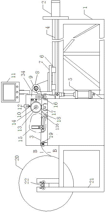
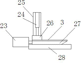
[0026] Depend on Figure 1-Figure 9 The shown V-belt bottom rubber and rope core bonding splitter includes a frame 1, which is sequentially provided with a bottom film support 21 for installing a bottom film 20, a rubber support roller 19 for clamping Primer roll 20 is primed and the primer feeding assembly 15, primer cutting assembly, driving roller 13 and driven roller 8 connected with the front and rear tensioning devices of the rope core are conveyed forward.

[0027] The bottom film support 21 is provided with a bottom film 20, and the bottom film support 21 is provided with a bottom film shaft 22 for installing the bottom film 20, and the rubber support roller 19 on the bottom film support 21 rear side is parallel to the bottom film shaft 22, and the bottom film support 21 is parallel to the bottom film shaft 22. The film 20 is coiled by rows of primers 3 , and the primers 3 drawn from the primer roll 20 enter the primer feeding assembly 15 from the rubber support roller...


PUM


Abstract

The invention discloses a V-belt base glue and rope core bonding divider, which comprises a rack, wherein a base glue coil support for installing a base glue coil, a base glue sending assembly used for clamping a base glue on the base glue coil and conveying the base glue forwards, a base glue cutting assembly, a driving roller, and a driven roller connected with a front and back rope core tensioning device are sequentially arranged on the rack from the front to the back, and the driving roller is arranged on a spindle connected with a power device; the base glue cutting assembly is provided with a cutter used for cutting off the base glue, and the cutter is connected with a telescopic device; a dividing assembly is arranged at the lower side between the driving roller and the driven roller, and comprises a lifting device and a blade bearing connected with the lifting device, and a blade shaft and a plurality of round blades arranged on the blade shaft are arranged on the blade bearing; a counting sensor for detecting a base glue head is arranged on the rack, and the power device, the base glue sending assembly, the telescopic device, the lifting device, the front and back rope core tensioning device and the counting sensor are connected with a control system through signals. The V-belt base glue and rope core bonding divider can achieve an automation object.

Description

technical field [0001] The invention relates to a V-belt bottom glue and rope core bonding and dividing machine. Background technique [0002] The V-belt primer bonding process in production, in the production process, remove one of the pre-divided belt blanks (belt drums) and hang it on the front and rear belt rollers of the machine, and then glue the primer head manually Close on the belt blank, step on the pedal clutch, let the main shaft drive the driving belt roller to rotate, and then drive the bottom rubber while the belt drum is rotating, so that the bottom rubber sticks to the belt drum, and press the bottom rubber tightly through the lower pressure roller After turning around for a week, cut off the primer manually with scissors. After connecting the joints and removing the core, only one piece can be processed at a time. This bonding method is inefficient and labor-intensive. When the width of the new cut is uneven, the problem of improper bonding between the tap...

Claims


Application Information

Patent Timeline
IPC IPC(8): B65H37/04B65H35/02B65H35/06B65H43/00
Inventor 要银安唐全胜张俊龙要建安
Owner 要银安
Why Eureka
Eureka Blog
Learn More