
Corner connecting fitting for surface tubes

A corner connection and corner joint technology, applied in building structures, stepped structures, buildings, etc., can solve the problems of adapting and adjusting the angle range, unable to meet the building structure, affecting the installation efficiency, etc., to improve the installation efficiency and visual effect. Improved, simple structure

Active Publication Date: 2014-04-02
HUNAN GOLDWELL NEW MATERIALS TECH CO LTD
View PDF11 Cites 7 Cited by
  • Summary
  • Abstract
  • Description
  • Claims
  • Application Information

AI Technical Summary

Problems solved by technology

The traditional right-angle guardrail cannot meet the existing building structure
In the prior art, most of the corner joints used at the corners of surface pipes are cast aluminum parts. For corners with different angles, technicians must make corner joints with corresponding angles for use. The cost is too high, and the angle range cannot On-site adaptation and adjustment seriously affect the installation efficiency

Method used


Image

  • Corner connecting fitting for surface tubes
  • Corner connecting fitting for surface tubes
  • Corner connecting fitting for surface tubes

Examples


Embodiment 1

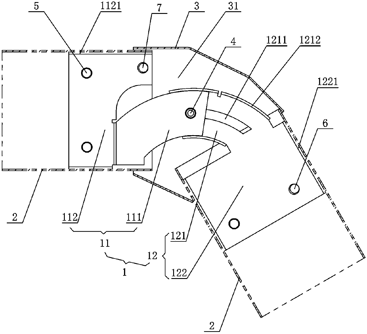
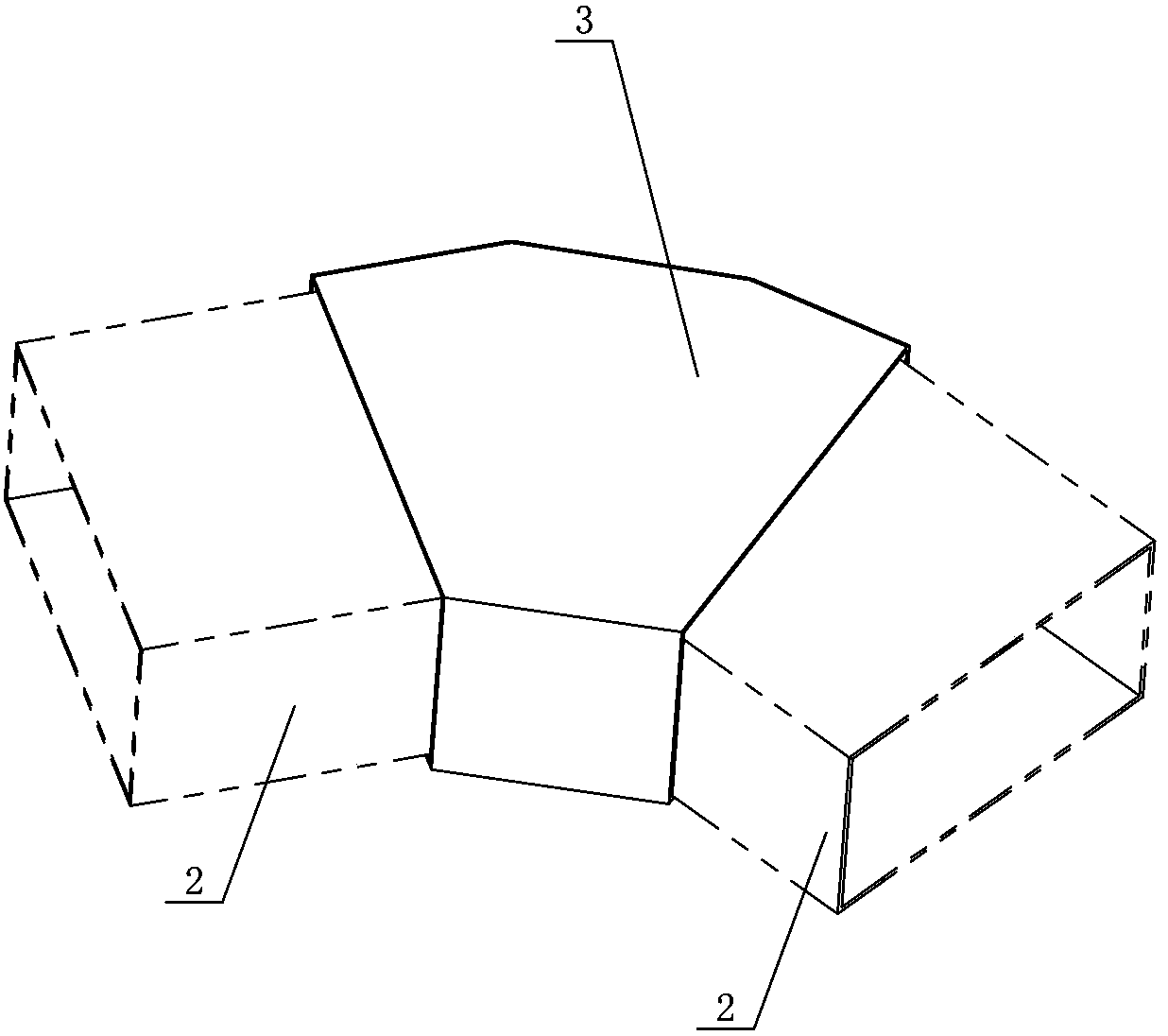
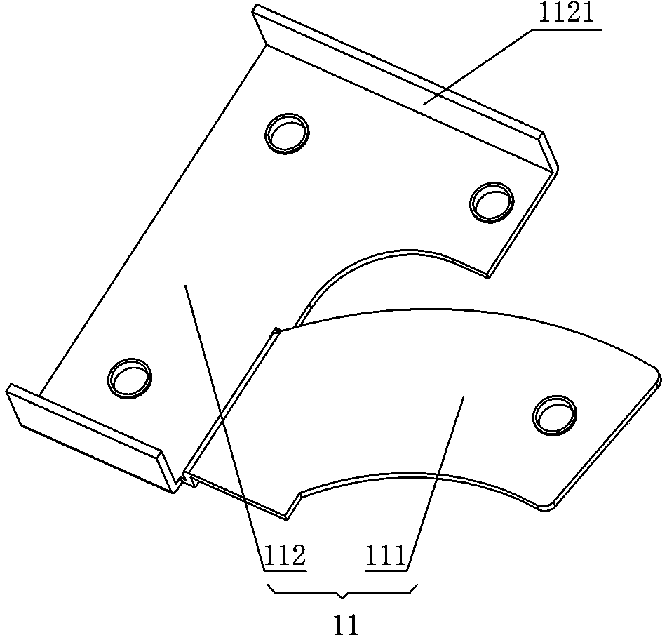
[0030] Figure 1 to Figure 7 It shows the first embodiment of the corner connection fittings for surface pipes of the present invention, the connection fittings include a corner joint 1, the corner joint 1 includes a connecting female part 11 and a connecting sub-part 12, and the connecting female part 11 and the connecting sub-part 12 are respectively inserted into the two surface tubes 2 and fixedly connected with the surface tubes 2. The connecting parent part 11 is provided with a first sliding part 111 extending to the outside of the surface tube 2, and the connecting child part 12 is provided with the first sliding part 111. The second sliding part 121 that cooperates with the first sliding part 111 and can slide in an arc shape along the first sliding part 111 has a simple structure and is easy to install. The combination of the second sliding part 121 and the first sliding part 111 The second sliding part 121 can slide along the first sliding part 111, that is, the ang...

Embodiment 2

[0040] Figure 8 to Figure 9It shows the second embodiment of the corner connection fitting for surface pipes of the present invention, which is basically the same as Embodiment 1, the difference is only that: the first sliding part 111 is bent on both sides for connecting with the second sliding part 111. The flange 1111 that the rotating part 121 is against, the flange 1111 is set so that when the first fastener 4 is tightened, the flange 1111 will be stretched and deformed to be tightly connected with the arc-shaped rib 1212, which greatly improves the connection. The fastening effect between the parent part 11 and the connecting sub-part 12.


PUM


Abstract

The invention discloses a corner connecting fitting for surface tubes. The corner connecting fitting comprises a corner connector, wherein the corner connector comprises a main connecting piece and a secondary connecting piece; the main connecting piece and the secondary connecting piece are respectively inserted into two surface tubes and are fixedly connected with the surface tubes; the main connecting piece is provided with a first sliding turning part which extends out of the surface tubes; the secondary connecting piece is provided with a second sliding turning part which is matched with the first sliding turning part and is capable of sliding and turning along the first sliding and turning part; two surface tubes are wrapped and covered with a decoration shell at the corner part; after the surface tubes are turned and the second sliding and turning part is driven to slide to a preset position, the decoration shell is respectively connected with the main connecting piece and the secondary connecting piece in a fastened manner through a first fastening piece. The connecting fitting has the advantages of simple structure, convenience in mounting, attractiveness in appearance and capability in matching and adjusting on site.

Description

technical field [0001] The invention mainly relates to the assembly technology of pipe connection, in particular to a corner connection fitting for surface pipes. Background technique [0002] In the field of guardrails, the surface pipes at the corners are generally connected through corner joints. However, due to the more and more changes in the shape of the building, there are many structures such as arc corners, so the requirements for products such as balcony guardrails Higher and higher. The traditional right-angle guardrail cannot meet the existing building structure. In the prior art, most of the corner joints used at the corners of surface pipes are cast aluminum parts. For corners with different angles, technicians must make corner joints with corresponding angles for use. The cost is too high, and the angle range cannot On-site adaptation and adjustment seriously affect the installation efficiency. Contents of the invention [0003] The technical problem to b...

Claims


Application Information

Patent Timeline
IPC IPC(8): E04F11/18
Inventor 谢斌泉
Owner HUNAN GOLDWELL NEW MATERIALS TECH CO LTD
Learn More