High-compressive hydraulic cylinder

A technology of hydraulic cylinder and cylinder block, applied in the direction of engine, wind power generation, wind engine control, etc., can solve the problems of unsatisfactory sealing effect, low reliability, low stability, inability to withstand high pressure, etc., and achieve guaranteed performance. , good wear resistance, increase the effect of dynamic and static sealing performance

Inactive Publication Date: 2014-04-02
贵州永兴风能制动器有限责任公司
View PDF7 Cites 4 Cited by
  • Summary
  • Abstract
  • Description
  • Claims
  • Application Information

AI Technical Summary

Problems solved by technology

Combined sealing elements are developed on the basis of O-rings, double-lip dust-proof rings and Y-rings in recent years. Dust ring plus Y-ring and other sealing rings, the sealing mechanism of the combined sealing element is basically the same as the sealing mechanism of elastic material seals such as O-ring, double-lip dust ring plus Y-ring, etc. There has always been a problem of medium leakage, and the sealing effect is also poor. It is not very ideal, and it cannot withstand high pressure; like O-rings, double-lip dust-proof rings and Y-rings, it will also appear unstable due to rigid material support rings; the existing hydraulic pressure The cylinder is prone to medium leakage, low reliability and stability, and short working life

Method used


Image

  • High-compressive hydraulic cylinder

Examples


Embodiment Construction

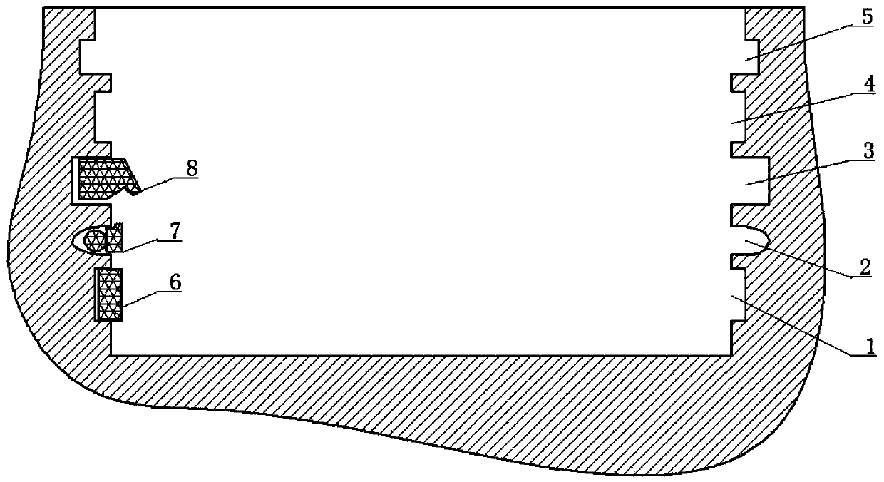
[0013] The present invention will be further described below in conjunction with accompanying drawing and specific embodiment:

[0014] As shown in Figure 1, a high-pressure hydraulic cylinder includes a U-shaped cylinder body, and the inner wall of the cylinder body has a bottom guide ring groove 1, a sealing ring groove 2 and a dust-proof ring groove 5 from bottom to bottom, and guides at the bottom. The guide ring 6 is embedded in the ring groove 1, the sealing ring groove 2 is U-shaped, the sealing ring 7 is embedded in the sealing ring groove 2, and the sealing ring 7 is a Ster seal sealing ring. There is also a secondary sealing ring groove 3 in between, the secondary sealing ring groove 3 is a square structure, the secondary sealing ring groove 3 is inlaid with a secondary sealing ring 8, and the part embedded in the secondary sealing ring groove 3 is a square structure, protruding Some are inverted V-shaped structures.

[0015] Among them, the Ster seal sealing ring i...


PUM


Abstract

The invention discloses a high-compressive hydraulic cylinder and belongs to the technical field of sealing application in wind generator brakes. The high-compressive hydraulic cylinder comprises a U-shaped cylinder body. The inner wall of the cylinder body is provided with a bottom guide circular groove, a seal ring groove and a dust ring groove from bottom to top. A guide ring is embedded into the bottom guide circular groove. A seal ring is embedded into the seal ring groove. The seal ring is a Simrit seal ring. A second seal ring groove is arranged between the seal ring groove and the dust ring groove. A second seal ring is embedded into the second seal ring groove. Hydraulic pressure in the cylinder body drives, from the lower portion of the Simrit seal ring, the Simrit seal ring to form hermetic fit with the surface of a piston; when the hydraulic pressure breaks through the Simrit seal ring, the inverted-V-shaped structure of the second seal ring blocks the hydraulic pressure, drives the hydraulic pressure to react on the upper portion of the Simrit seal ring and downwardly drives the Simrit seal ring, and under the action of upper and lower hydraulic pressures, the Simrit seal ring forms a stable seal structure.

Description

technical field [0001] The invention belongs to the technical field of wind power generator brake seal application, and in particular relates to a high pressure-resistant hydraulic cylinder. Background technique [0002] A conventional hydraulic cylinder consists of an end face, a cylinder body, a piston rod, a piston and a sealing ring. The key technology is the sealing technology for the cylinder body. The dynamic sealing of the piston adopts O-rings, double-lip dust-proof rings and Y rings for a long time. Type ring and combined sealing element sealing technology. Among them, the O-ring structure has good extrusion resistance, and a large gap can be maintained between the piston rod and the inner wall of the piston chamber. This sealing structure has good dynamic and static sealing performance, small friction, no crawling, no sticking phenomenon, good wear resistance, stable size, not affected by temperature, has excellent buffering effect on strong impact pressure, and ...

Claims


Application Information

Patent Timeline
Patent Type & Authority Applications(China)
IPC IPC(8): F16D65/14F03D7/00F16D121/04F16D125/08
CPCY02E10/723Y02E10/72
Inventor 吴胜勇
Owner 贵州永兴风能制动器有限责任公司
Why Eureka
Try Eureka