

Speed reducer testing equipment
A technology for testing equipment and reducers, which is applied in the field of construction machinery, can solve the problems of high cost of reducer test equipment and high price of large brakes, and achieve the effect of cost saving
- Summary
- Abstract
- Description
- Claims
- Application Information
AI Technical Summary
Problems solved by technology
Method used
Image


Examples
Embodiment Construction
[0019] The present invention will be described in detail below by means of drawings and embodiments.
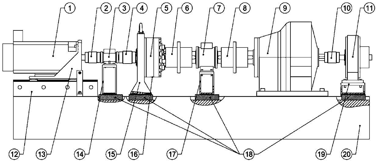
[0020] refer to figure 1 , figure 1 is a structural schematic diagram of the reducer testing equipment of the first embodiment. In this embodiment, the main mechanical structure of the reducer testing equipment includes a support platform 20 and a servo spindle motor 1 arranged on the support platform 20, a first rotational speed torque sensor 3, a second rotational speed torque sensor 7, a transmission 9, Brake 11, temperature sensor 16, motor support 13, first sensor support 14, test reducer support 15, second sensor support 17, brake support 19, positioning block 18, first coupling 2, second coupling 4. The third coupling 6 , the fourth coupling 8 and the fifth coupling 10 .
[0021] Wherein, the first coupling 2 is connected between the output shaft of the servo spindle motor 1 and the input shaft of the first rotational speed torque sensor 3 . The second coupling 4 i...
PUM
 Abstract
Description
Claims
Application Information