Cache allocation method and device

A cache allocation and sub-cache technology, applied in the computer field, can solve problems such as cache block division and unreasonable allocation

Active Publication Date: 2014-04-02
COMBA TELECOM SYST CHINA LTD
View PDF5 Cites 12 Cited by
  • Summary
  • Abstract
  • Description
  • Claims
  • Application Information

AI Technical Summary

Problems solved by technology

[0006] The embodiment of the present invention provides a cache allocation method and device

Method used


Image

  • Cache allocation method and device
  • Cache allocation method and device
  • Cache allocation method and device

Examples


Embodiment 1

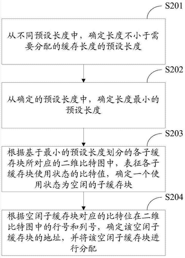
[0032] Embodiment 1 of the present invention provides a buffer allocation method, such as figure 2 mentioned, specifically include:

[0033] S201. From different preset lengths, determine a preset length whose length is not less than the buffer length to be allocated.

[0034] S202. From the determined preset lengths, determine a preset length with the smallest length.

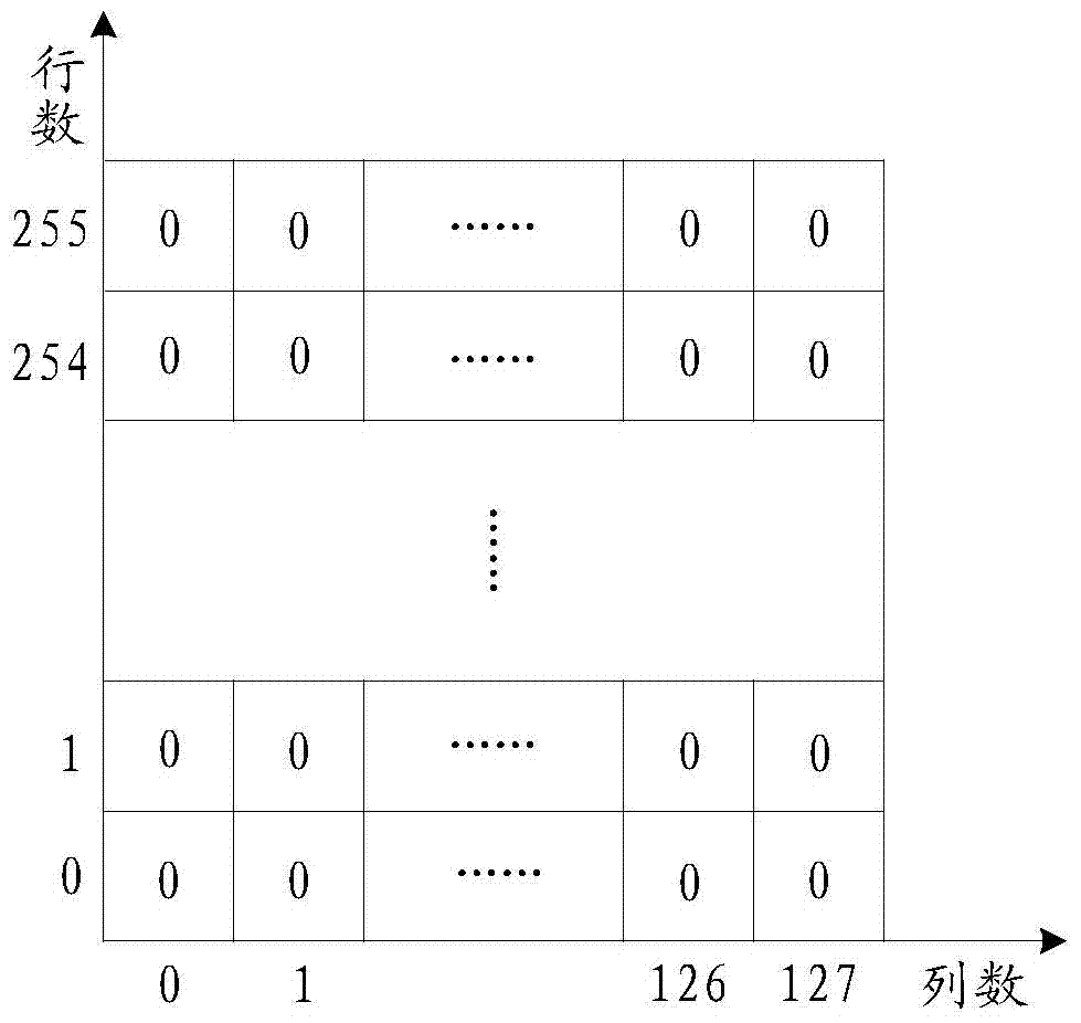
[0035] S203. Determine a sub-cache block whose usage state is idle according to the bit values ​​in the two-dimensional bitmap corresponding to each sub-cache block divided based on the preset length with the smallest length determined in S202, representing the use status of each sub-cache block, Wherein, the two-dimensional bitmap is a corresponding two-dimensional bitmap established for each sub-cache block divided based on different preset lengths, and each bit in the two-dimensional bitmap corresponds to each bit in the two-dimensional bitmap One-to-one correspondence between the sub-cache blocks, the b...

Embodiment 2

[0055] In Embodiment 2 of the present invention, a buffer allocation method is provided, such as Figure 4 shown, including the following steps:

[0056] S401. From different preset lengths, determine a preset length whose length is not less than the buffer length to be allocated.

[0057] S402. From the determined preset lengths, determine a preset length with the smallest length.

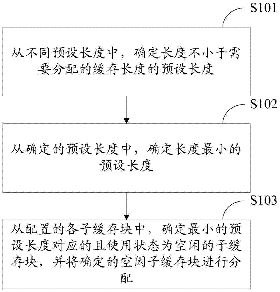
[0058] S403. From the configured sub-cache blocks, determine the sub-cache blocks corresponding to the minimum preset length determined in S402 and whose usage status is free, and allocate the determined free sub-cache blocks.

[0059] S404. Update the usage state of the allocated sub-cache block to occupied.

[0060] S405. From each sub-cache block divided based on each first preset length, determine a first sub-cache block that has one of the following positional relationships with the allocated sub-cache block, wherein the first preset length is all preset lengths Each preset length except t...

Embodiment 3

[0067] In Embodiment 3 of the present invention, a buffer allocation method is provided, such as Figure 5 shown, including the following steps:

[0068] S501. From different preset lengths, determine a preset length whose length is not less than the buffer length to be allocated.

[0069] S502. From the determined preset lengths, determine a preset length with the smallest length.

[0070] S503. From the configured sub-cache blocks, determine the sub-cache blocks corresponding to the minimum preset length determined in S502 and whose usage status is free, and allocate the determined free sub-cache blocks.

[0071] S504. Update the usage state of the allocated sub-cache block to occupied.

[0072] S505. From each sub-cache block divided based on each first preset length, determine a first sub-cache block that has one of the following positional relationships with the allocated sub-cache block, wherein the first preset length is all preset lengths Each preset length except t...


PUM


Abstract

An embodiment of the invention provides a cache allocation method and device. The cache allocation method comprises determining the preset lengths which are not less than the cache lengths which need to be allocated in different preset lengths; determining the smallest preset length in the determined preset lengths; determining sub-cache blocks which are corresponding to the smallest preset length and idle in use state in allocated sub-cache blocks and allocating the determined idle sub-cache blocks, wherein the same cache block is divided into the plurality of sub-cache blocks which are equal in length based on the different preset lengths. Compared with the prior art, the problem that the fixed size of sub-cache blocks are allocated no matter caches needing to be allocated are large or small is solved and accordingly the cache utilization is improved and the division and the allocation of the cache blocks can be reasonable. The cache allocation method and device relates to the computer technical field.

Description

technical field [0001] The present invention relates to the field of computer technology, in particular to a cache allocation method and device. Background technique [0002] The management and allocation of buffers are widely used in the fields of computer programming and network communication. Because in many cases, some temporary data needs to be temporarily stored. For example, the operation of a program needs to allocate a cache for the program, and the data packet received from the computer network needs to allocate a cache for the data packet. In the prior art, there are mainly the following methods for cache management and allocation: [0003] The first is a cache management method based on a first-in-first-out queue. In this method, the cache block is divided into fixed-length sub-cache blocks, and a queue is used to store the addresses of each free sub-cache block. When a sub-cache block needs to be allocated, a sub-cache block address is taken out from the head ...

Claims


Application Information

Patent Timeline
IPC IPC(8): G06F12/08G06F12/0871
Inventor 赵剑川贾克明刘福元
Owner COMBA TELECOM SYST CHINA LTD
Why Eureka
Try Eureka