Microwave sulphur lamp on basis of electron cyclotron resonance discharge

An electron cyclotron resonance and microwave technology, which is applied in the parts and circuits of discharge lamps and gas discharge lamps, can solve the problems of slow start-up time and unstable start-up process of microwave sulfur lamps, achieve rapid ignition process, improve lifespan, Improve the effect of the mean free path

Inactive Publication Date: 2014-04-02
UNIV OF ELECTRONIC SCI & TECH OF CHINA
View PDF5 Cites 4 Cited by
  • Summary
  • Abstract
  • Description
  • Claims
  • Application Information

AI Technical Summary

Problems solved by technology

[0008] The technical problem to be solved by the present invention is to provide a microwave sulfur lamp based on electron cyclotron resonanc

Method used


Image

  • Microwave sulphur lamp on basis of electron cyclotron resonance discharge
  • Microwave sulphur lamp on basis of electron cyclotron resonance discharge
  • Microwave sulphur lamp on basis of electron cyclotron resonance discharge

Examples


Embodiment 1

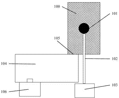
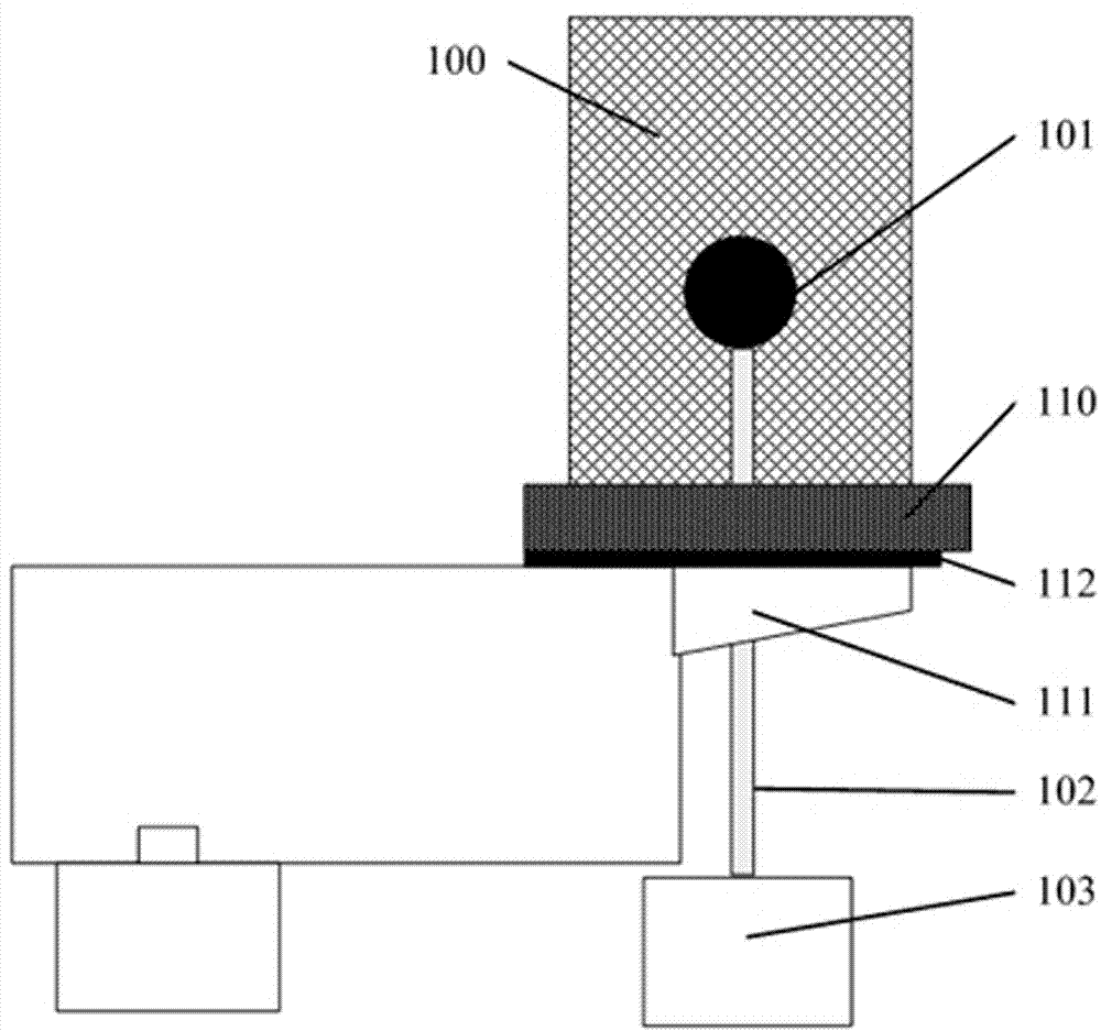
[0031] Such as figure 2 As shown, the magnet 110 is placed at the bottom of the resonant cavity 100, and can be placed inside or outside the resonant cavity 100. In order to better protect the magnet 110, it may be necessary to fill a heat insulating material between the magnet 110, the metal waveguide 104 and the resonant cavity 100. 112, or put a heat-shielding reflector on top of the magnet.

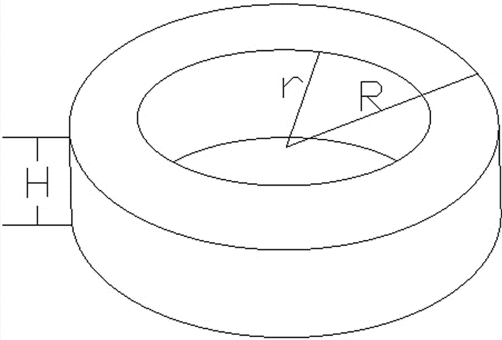
[0032] Such as image 3 As shown, the material of the magnet 110 used in this embodiment is smco28, the inner radius r is consistent with the outer radius R of the metal resonant cavity 100, the outer radius R is 40 mm, and the height H is 20 mm. The distribution of the magnetic field generated by the magnet 100 along the central axis of the magnet is as follows: Figure 4 As shown, at the center of the bulb 101, the axial magnetic field intensity is equal to 875Gs. If the microwave source uses a 2.45GHz magnetron, the electron cyclotron resonance discharge condition is established...

Embodiment 2

[0034] Such as Figure 5 As shown, the magnet 110 is placed in the middle of the resonant cavity 100 , and the axis of the magnet 110 is at the same height as the center of the bulb 101 .

[0035] The material of the magnet 110 used in this embodiment is smco28, the inner radius r is consistent with the outer radius of the metal resonant cavity 100, the outer radius R of the magnet 110 is 38mm, and the height H is 5mm. The distribution of the magnetic field generated by the magnet 110 along the central axis of the magnet is as follows: Image 6 As shown, at the central position of the bulb 101, the peak value of the axial magnetic field intensity is equal to 900Gs, so there are two positions within the range of the bulb where the axial magnetic field intensity is equal to 875Gs. There are two areas in the lamp that meet the electron cyclotron resonance discharge condition, and the electrons in the lamp can obtain continuous heating effect better.


PUM

PropertyMeasurementUnit
Outer radiusaaaaaaaaaa
Heightaaaaaaaaaa

Abstract

The invention discloses a microwave sulphur lamp on the basis of electron cyclotron resonance discharge. The microwave sulphur lamp comprises a magnet for generating a magnetic field and a corresponding fixing assembly and is characterized in that the magnet provides the specific magnetic field distribution, so that in the igniting and light emitting process of the microwave sulphur lamp, plasmas in a lamp bulb meet the electron cyclotron resonance condition. According to the invention, the igniting process of the microwave sulphur lamp is more rapid and stable and meanwhile, the service life of the lamp bulb is prolonged. According to the invention, cyclotron resonance is introduced, so that electrons in the lamp bulb take the cyclotron motion, a mean free path of motion of the electrons is improved and energy of the electrons is further promoted, and thus, adsorption efficiency of the plasmas on microwaves is improved.

Description

technical field [0001] The invention relates to the field of plasma lighting, in particular to the improvement of ignition and luminous efficiency in microwave sulfur lamps. Background technique [0002] Microwave sulfur lamp is a kind of high-efficiency energy-saving green electrodeless light source. Microwave sulfur lamps have the following advantages: (1) No electrode pollution (mercury pollution); (2) High luminous efficiency (light bulb luminous efficiency can reach more than 90lm / w); (3) Long life (>60000 hours); (4 ) Good color rendering (Tc=5500K—6500K, Ra>80); (5) Good light maintenance rate (light decay is less than 3% when ignited for 10,000 hours); (6) Continuous spectrum, low ultraviolet and infrared radiation, comfortable for the human body high degree. [0003] Microwave sulfur lamps use the molecular radiation of sulfur vapor to produce continuous visible light. First, the microwave energy breaks down the argon gas filled in the bulb to make it disch...

Claims


Application Information

Patent Timeline
IPC IPC(8): H01J65/04H01J61/54
Inventor 黄桃金晓林李斌李建清王茂碧卢辉杨中海
Owner UNIV OF ELECTRONIC SCI & TECH OF CHINA
Why Eureka
Try Eureka