Outer rotor synchronous magnetic resistance motor rotor

A synchronous reluctance motor and outer rotor technology, applied in the direction of magnetic circuit rotating parts, magnetic circuit shape/style/structure, etc., can solve the problem of unspecified thickness, width, distribution, strength of magnetically conductive and non-magnetically conductive channels. and stiffness, reduce reluctance torque and other problems, to achieve the effect of convenient manufacturing, improve reluctance torque, improve inductance difference

Active Publication Date: 2014-04-02
HANGZHOU EASITECH
View PDF8 Cites 3 Cited by
  • Summary
  • Abstract
  • Description
  • Claims
  • Application Information

AI Technical Summary

Problems solved by technology

1. The structure has a magnetic bridge, that is, on the side of the rotor close to the air gap, there is a magnetic material to connect the magnetic channels to each other. This structure will weaken the difference between the reluctance of the orthogonal and direct axes, thereby reducing the reluctance torque. It is not applicable and requires a large Power density applications; 2. There is a mechanical weak link between the two hollow grooves near the air gap side of the rotor structure, which is connected by a thin structure, and its strength and rigidity are poor, so it is not suitable for large torque or large centrifugal force Occasion application
3. The application did not clarify the internal laws of the thickness, width, and distribution of each magnetically conductive channel and non-magnetically permeable channel, which is not conducive to actual design and application
These defects constitute the limitations of its engineering application

Method used


Image

  • Outer rotor synchronous magnetic resistance motor rotor
  • Outer rotor synchronous magnetic resistance motor rotor
  • Outer rotor synchronous magnetic resistance motor rotor

Examples


Embodiment Construction

[0027] The present invention will be further described below in conjunction with specific examples, but the present invention is not limited to these specific implementations. Those skilled in the art will realize that the present invention covers all alternatives, modifications and equivalents as may be included within the scope of the claims.

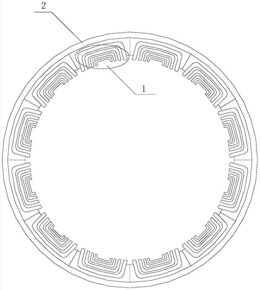
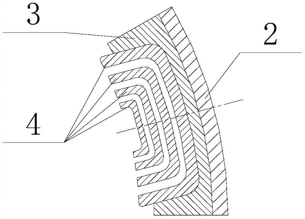
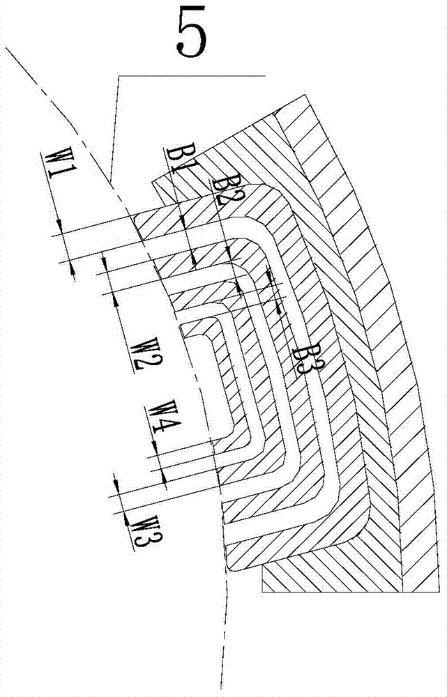
[0028] refer to Figure 1-5 , an outer rotor synchronous reluctance motor rotor, including a rotor yoke 2, the rotor yoke 2 is installed with an even number of pole units 1 uniformly distributed along the circumference, the pole unit 1 includes a mounting frame 3, the mounting frame Several magnetic tracks 4 arranged in sequence along the radial direction are installed inside 3 , and gaps are provided between adjacent magnetic tracks 4 . The mounting frame 3 and the rotor yoke 2 are reliably connected, and the connection method may be interference, bonding, welding, expansion, screw fastening and the like. The present invention has ...


PUM


Abstract

The invention provides an outer rotor synchronous magnetic resistance motor rotor, which comprises a rotor yoke, wherein an even number of magnetic pole units in uniform distribution along the circumference are arranged on the rotor yoke, each magnetic pole unit comprises an installing frame, a plurality of magnetic passages sequentially ranged in the radial direction are arranged in the installing frame, and gaps are arranged between the adjacent magnetic passages. The outer rotor synchronous magnetic resistance motor rotor has the beneficial effects that a magnetic-bridge-free structure is adopted, mutually connected magnetic guide parts are not adopted between the magnetic passages, and the alternating current and direct current axis inductance differences can be easily improved, so the magnetic resistance torque is increased, and the outer rotor synchronous magnetic resistance motor rotor is suitable for occasions requiring high-power density. In the weak link without stress concentration, the rigidity and the intensity of each magnetic passage used as a carrying main body can be guaranteed, and the outer rotor synchronous magnetic resistance motor rotor is suitable for being applied to large-torque or large-centrifugal-force occasions; the processing and the manufacturing are convenient, a plurality of magnetic pole units are spliced after the single processing of each magnetic pole unit is completed, the structure of each magnetic pole unit is simple, no complicated curve surface exits, the processing of single parts is convenient, complicated process measures are not needed, and the outer rotor synchronous magnetic resistance motor rotor is suitable for engineering application.

Description

technical field [0001] The invention relates to a motor rotor, in particular to an outer rotor synchronous reluctance motor rotor. Background technique [0002] A synchronous reluctance motor is a motor that relies on reluctance torque to operate. The reluctance torque is rooted in the rotor structure with unequal reluctance of the orthogonal and direct axes. The greater the difference between the reluctance of the orthogonal and direct axes, the greater the reluctance torque. Compared with the induction motor, this type of motor has no rotor side winding, can obtain higher efficiency, and has better speed regulation characteristics. Intersect with permanent magnet motors, which have no permanent magnets, are less costly, and have no risk of permanent magnet demagnetization. Therefore, this type of motor is emerging in industries such as elevators, home appliances, and vehicle drives. [0003] Patent Nos. CN103098346A, CN1881757B, CN101443982A, CN101039059A and other pa...

Claims


Application Information

Patent Timeline
IPC IPC(8): H02K1/24
Inventor 洪涛方卫中朱彤华晋兆海
Owner HANGZHOU EASITECH
Why Eureka
Try Eureka