Scene monitoring method and moving target tracking method based on GIS (Geographic Information System) map

A GIS map and moving target technology, applied in the direction of image communication, color TV parts, TV system parts, etc., can solve the problem of all-round scene monitoring without considering the pan-tilt camera

Inactive Publication Date: 2014-04-02
ZHEJIANG UNIVIEW TECH CO LTD
View PDF8 Cites 26 Cited by
  • Summary
  • Abstract
  • Description
  • Claims
  • Application Information

AI Technical Summary

Problems solved by technology

The method and the system do not consider how to achieve the

Method used


Image

  • Scene monitoring method and moving target tracking method based on GIS (Geographic Information System) map
  • Scene monitoring method and moving target tracking method based on GIS (Geographic Information System) map
  • Scene monitoring method and moving target tracking method based on GIS (Geographic Information System) map

Examples


Embodiment 1

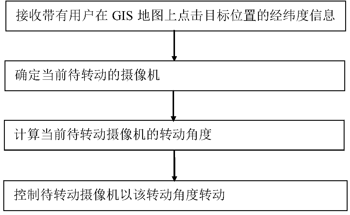
[0024] Please refer to figure 1 The flow chart of this embodiment is shown. The steps of the process are specifically performed by the device controlling the camera:

[0025] Step 11. Receive latitude and longitude information carrying the target location clicked by the user on the GIS map.

[0026] Step 12: Determine the current camera to be rotated according to the latitude and longitude information of the target location and the camera location information saved by the control device.

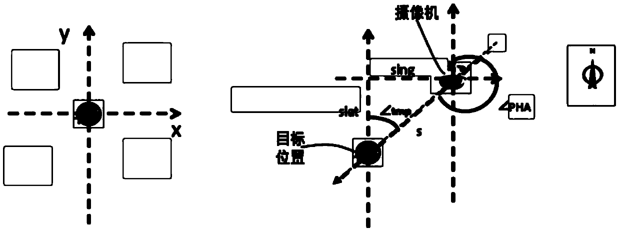
[0027] Step 13. Calculate the rotation angle of the camera to be rotated according to the latitude and longitude information of the target location and the latitude and longitude information of the installation position of the camera to be rotated.

[0028] Step 14: Send the rotation angle information to the camera to be rotated to control the camera to rotate to the target position on the GIS map for monitoring.

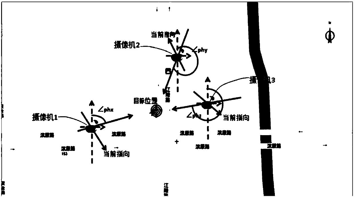
[0029] The cameras in this embodiment are all cameras that can rotate 360 ...

Embodiment 2

[0050] This embodiment provides a method for tracking a moving target. The mobile target in this embodiment needs to be able to send information about its location to the control device. The specific operations performed by the control device are as follows:

[0051] Step 41: Periodically receive a signal transmitted by the moving target, the signal carrying the latitude and longitude information of the moving target.

[0052] Step 42: Determine the current camera to be rotated according to the longitude and latitude information of the location of the moving object and the camera location information saved by the control device.

[0053] Step 43: Calculate the rotation angle of the camera to be rotated according to the latitude and longitude information of the location of the moving object and the latitude and longitude information of the camera to be rotated.

[0054] Step 44: Send the rotation angle information to the camera to be rotated to control the camera to rotate to...


PUM


Abstract

The scheme of the invention provides a scene monitoring method based on a GIS (Geographic Information System) map. The method comprises the following steps: receiving longitude and latitude information carrying a click target position of a user on the GIS map; determining a current camera waiting to rotate according to longitude and latitude information of the target position and the longitude and latitude information of the position of the camera saved in control equipment; calculating the rotating angle of the camera waiting to rotate according to the longitude and latitude information of the target position and the longitude and latitude information of the mounting position of the camera waiting to rotate; transmitting the rotating angle information of the camera waiting to rotate in order to control the camera waiting to rotate to rotate to the target position on the GIS map for monitoring. According to the scheme of the invention, a scene-based monitoring service is started on the basis of a position to be monitored on the GIS map, so that simultaneous all-dimensional and multi-angle monitoring of the target position is realized automatically.

Description

technical field [0001] The invention relates to the field of video monitoring, in particular to a GIS map-based scene monitoring method and a moving target tracking method. Background technique [0002] With the construction of a safe city, the demand for surveillance based on GIS maps continues to grow. Marking surveillance cameras on GIS maps can achieve the purpose of more intuitively calling surveillance videos based on GIS maps. [0003] The Chinese patent titled "GPS and GIS-based intelligent visual sensor network moving target relay tracking system" discloses a GPS and GIS-based intelligent visual sensor network moving target relay tracking system. The system includes a number of monitoring camera units, each monitoring camera unit includes a monitoring camera, embedded or equipped with a GPS receiving positioning module and a wired / wireless communication module, through which the monitoring camera unit collects video sequences in the monitoring area, and the wired / wi...

Claims


Application Information

Patent Timeline
IPC IPC(8): H04N5/232H04N7/18
Inventor 丁立新
Owner ZHEJIANG UNIVIEW TECH CO LTD
Why Eureka
Try Eureka