X-ray detector system for a computed tomography scanner and computed tomography device

A technology of tomography and detectors, applied in the directions of radiological diagnosis instruments, computed tomography scanners, radiation measurement, etc., can solve problems such as troublesome and expensive, and achieve the effect of realizing cost and simple installation

Inactive Publication Date: 2014-04-09
SIEMENS HEALTHCARE GMBH
View PDF4 Cites 6 Cited by
  • Summary
  • Abstract
  • Description
  • Claims
  • Application Information

AI Technical Summary

Problems solved by technology

These solutions are more or less cumbersome and expensive

Method used


Image

  • X-ray detector system for a computed tomography scanner and computed tomography device
  • X-ray detector system for a computed tomography scanner and computed tomography device
  • X-ray detector system for a computed tomography scanner and computed tomography device

Examples


Embodiment Construction

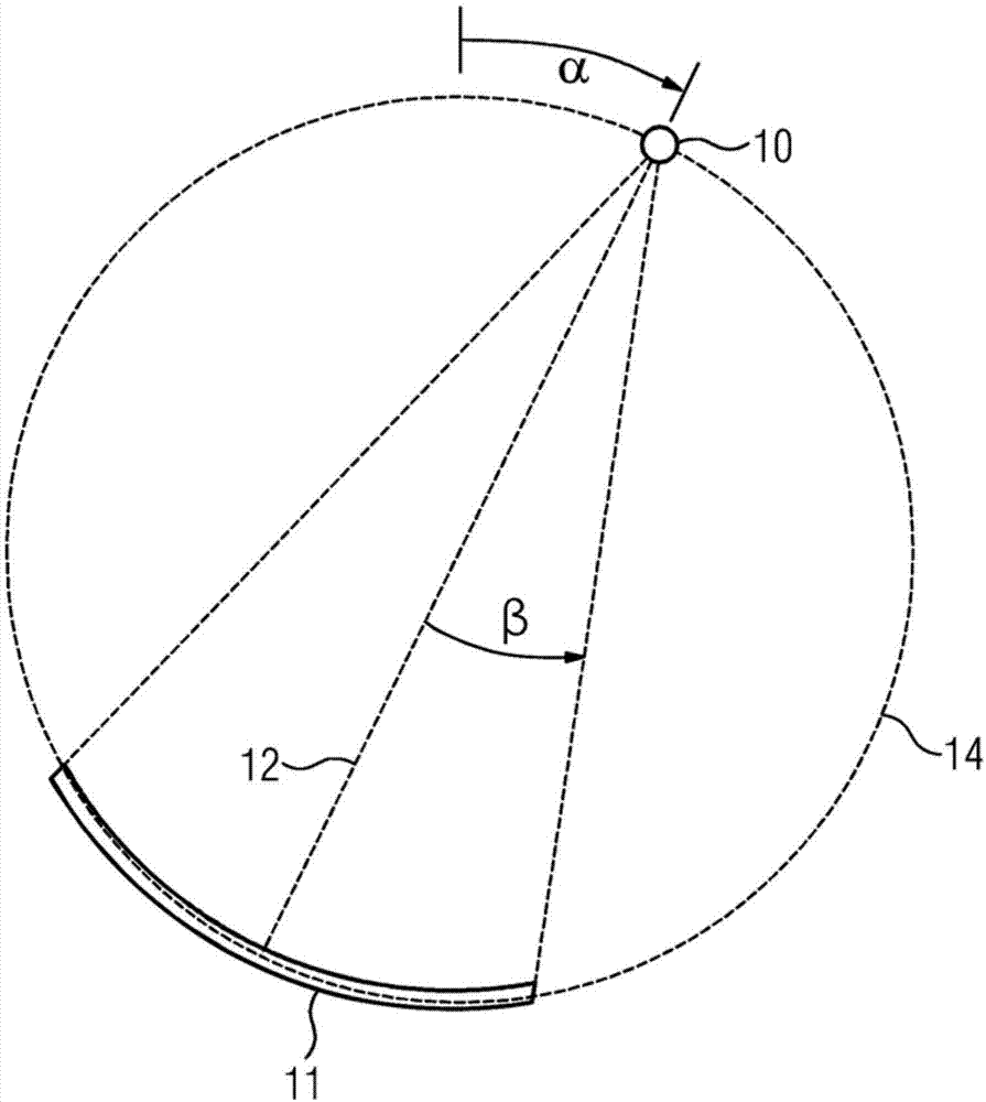
[0025] figure 1 The geometry of a known computed tomography scanner with an x-ray detector 11 with at least one detector row and an x-ray source with a focal point 10 is shown schematically. The x-ray detector 11 and the x-ray source are arranged opposite each other in a gantry (not shown) of a computed tomography scanner and are movable on a circular path 14 about the isocenter. The x-ray source emits x-rays, wherein a so-called central beam 12 is directed essentially at the center of the x-ray detector. The so-called fan angle β denotes the angular distance of the detector elements (pixel elements) from the central beam 12 . During the rotation of the gantry, a plurality of projection images are recorded at different projection angles α and then reconstructed accordingly, for example into a 3D volume image. The general acquisition and reconstruction of computed tomography images is known.

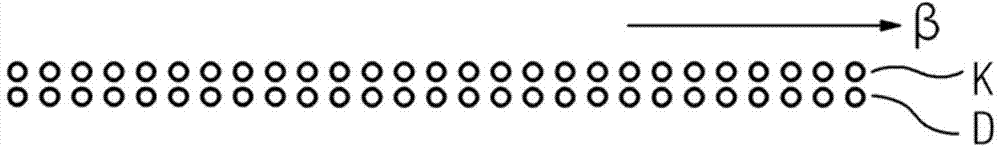
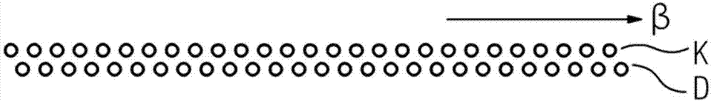
[0026]Known X-ray detectors 11 have a uniform grid, which determines the arrangeme...


PUM


Abstract

The present invention relates to an x-ray detector system for a computed tomography scanner. The x-ray detector system includes at least one detector row which includes a plurality of detector modules each having a plurality of detector elements. Along the at least one detector row, a first portion of the detector elements is arranged in a grid at a first grid spacing a1 in relation to its respective neighboring detector elements, and a second portion of the detector elements is arranged in a grid at a second grid spacing a2 in relation to its respective neighboring detector elements.

Description

technical field [0001] The invention relates to an X-ray detector system for computerized tomography and to a computerized tomography (CT machine), said X-ray detector system having at least one detector row, said detector A row has a plurality of detector modules, each of which has a plurality of detector elements, wherein along the at least one detector row, a first part of the detector elements is arranged in the same position relative to its respective adjacent detector element. A grid pitch is arranged in a grid, and the second subsection of detector elements is arranged in a grid with a second grid pitch relative to their respective detector elements. Background technique [0002] In modern computed tomography imaging, in order to improve the image plane (along the β direction, where β is the so-called fan angle, see for example figure 1 The sector angle represents the angular distance between the detector elements and the central beam 12; the central beam is the cent...

Claims


Application Information

Patent Timeline
Patent Type & Authority Applications(China)
IPC IPC(8): A61B6/03
CPCG01T1/2985G01N2223/501G01N23/046A61B6/584G01N2223/419
Inventor T.弗洛尔M.格拉斯拉克K.施蒂尔斯托弗
Owner SIEMENS HEALTHCARE GMBH
Why Eureka
Try Eureka