Spray drying equipment for circulating fluidized bed

A circulating fluidized bed and drying equipment technology, applied in spray evaporation, chemical instruments and methods, evaporator accessories, etc., can solve the problems of complex structure and low thermal efficiency, and achieve simple equipment structure, fast mass transfer speed, and moisture vaporization. fast effect

Active Publication Date: 2014-04-09
KUNMING TEKANG TECH CO LTD
View PDF5 Cites 0 Cited by
  • Summary
  • Abstract
  • Description
  • Claims
  • Application Information

AI Technical Summary

Problems solved by technology

Existing spray drying equipment generally has a large drying tower, which has the disadvantages of complex structure and low thermal efficiency.

Method used


Image

  • Spray drying equipment for circulating fluidized bed
  • Spray drying equipment for circulating fluidized bed
  • Spray drying equipment for circulating fluidized bed

Examples


no. 1 example

[0020] The first embodiment: a circulating fluidized bed spray drying equipment.

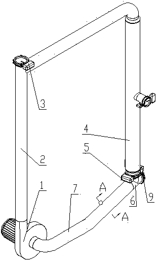
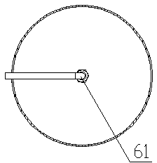
[0021] see figure 1 , figure 2 with image 3 , the circulating fluidized bed spray drying equipment includes fan 1, circulation pipeline I2, dust collector 4, regulating valve 5, inlet tee 6, circulation pipeline II7, the above components are blower 1 outlet, circulation pipeline I2, dust removal Air intake pipe 40 of device 4, ash discharge pipe 49 of dust collector 4, regulating valve 5, intake tee 6, circulation pipeline II 7, and fan 1 inlet are connected in order to form a circulation channel. A discharge valve 3 is installed on the feed port; another port of the air inlet tee 6 is an air inlet, and an air inlet valve 9 is installed on the air inlet; an atomizer 61 is installed in the circulation pipeline II7.

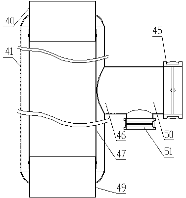
[0022] The dust collector 4 of the circulating fluidized bed spray drying equipment is a pulse bag dust collector. The pulse bag dust collector includes a housing 41, an air inl...

no. 2 example

[0023] The second embodiment: another circulating fluidized bed spray drying equipment.

[0024] see Figure 4 with Figure 5 , the circulating fluidized bed spray drying equipment includes a fan 1, a dust collector 29, a circulation pipeline I2, a dust collector 21, a pipeline A22, a dust collector 23, a pipeline B24, a dust collector 25, a pipeline C26, a dust collector 4, and a regulating valve 5 , Intake Tee 6, Circulation Pipeline Ⅱ7, Fan 27, Pipeline D28, the above components are outlet of Fan 1, Dust Collector 29 Intake Pipe 40, Dust Collector 29 Ash Discharge Pipe 49, Circulation Pipeline Ⅰ2, Dust Collector 21 Intake Pipe 40. Dust collector 21 ash discharge pipe 49, pipe A22, dust collector 23 intake pipe 40, dust collector 23 ash discharge pipe 49, pipe B24, dust collector 25 intake pipe 40, dust collector 25 ash discharge pipe 49, pipe C26, dust removal Air intake pipe 40 of device 4, ash discharge pipe 49 of dust collector 4, regulating valve 5, air intake tee 6, ...


PUM


Abstract

The invention discloses spray drying equipment for a circulating fluidized bed. According to the spray drying equipment for the circulating fluidized bed, a circulating channel is formed by a fan (1), a circulating pipeline I (2), a dust collector (4), a regulating valve (5), a three-way air inlet joint (6) and a circulating pipeline II (7). An atomizer is arranged in the circulating pipeline II (7). Under the action of the fan (1), air flow enters the circulating channel through an air inlet valve (9) and circularly flows at high speed, a liquid-state material is atomized through the atomizer, enters the circulating channel, goes into a fluidization state under the action of the high-speed air flow, and flows at high speed in the circulating channel, heat exchange and water exchange are quickly performed between the material and the air flow, and wet air is discharged along with air flow separated from the dust collector, so that the liquid-state material can be dried.

Description

technical field [0001] The invention relates to a spray drying equipment. Background technique [0002] Spray drying is a kind of drying that uses an atomizer to disperse a liquid or paste-like material into very fine mist-like particles, and contacts with hot air to remove most of the water in an instant, so that the solid matter in the material can be dried. method. Existing spray drying equipment generally has a drying tower with a large size, which has disadvantages such as complex structure and low thermal efficiency. Contents of the invention [0003] The technical problem to be solved by the present invention is to provide a circulating fluidized bed spray drying equipment with simple structure and high thermal efficiency. [0004] The technical solution of the present invention is: a circulating fluidized bed spray drying equipment, including fan, circulation pipeline I, dust collector, regulating valve, air inlet tee, circulation pipeline II, the above component...

Claims


Application Information

Patent Timeline
Patent Type & Authority Applications(China)
IPC IPC(8): B01D1/18B01D1/30B01D46/02B01D46/04
Inventor 贾平杜娟李继春
Owner KUNMING TEKANG TECH CO LTD
Why Eureka
Try Eureka