
Axial shiftable type abrasive wheel and intelligent adjustment device thereof

An intelligent adjustment and grinding wheel technology, which is applied to the parts of grinding machine tools, grinding/polishing equipment, metal processing equipment, etc., can solve the problems that the processing process does not meet the processing accuracy requirements, reduces work efficiency, and has a large amount of wear. Achieve the effect of improving the effective working area, ensuring the quality of processed parts, and reducing processing costs

Active Publication Date: 2014-04-09
QUANZHOU SHUANGYANG DIAMOND TOOL
View PDF5 Cites 49 Cited by
  • Summary
  • Abstract
  • Description
  • Claims
  • Application Information

AI Technical Summary

Problems solved by technology

Due to the working position of the grinding wheel, it is either fixed or at a certain angle to the surface to be processed, resulting in uneven wear on the working surface of the grinding wheel.
Traditionally, on the surface of the same normal working grinding wheel, after a period of use, it is found that a certain area has a large amount of wear, resulting in the subsequent machining process not meeting the required machining accuracy requirements; and under the same circumstances, another or several other Areas with less wear can continue to be used for machining, in which case the entire wheel must be replaced to meet machining needs
The above two situations not only increase the working time, reduce the working efficiency and increase the processing cost, but also cause the waste of precious materials, which is not conducive to environmental protection and sustainable production

Method used


Image

  • Axial shiftable type abrasive wheel and intelligent adjustment device thereof
  • Axial shiftable type abrasive wheel and intelligent adjustment device thereof
  • Axial shiftable type abrasive wheel and intelligent adjustment device thereof

Examples


Embodiment Construction

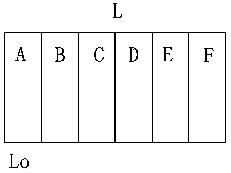
[0021] The theoretical basis of the present invention is as follows: with reference to figure 1 As shown, the grinding wheel with a total length of L is divided into six sections of A-F with axially equal lengths, and each section has a length of L0. After the grinding wheel is installed correctly and works normally for a period of time, the wear amount of the C, D, and E sections is the largest. It can be seen that these 3 sections are the working area, and the length is 3*L0. The wear of the B and F sections is small, and the A section is worn. Minimum amount. When the wear amount of C, D, and E section areas reaches the limit value, it is necessary to replace the new grinding wheel at this time to meet the production demand. However, the present invention pushes and adjusts the position of the grinding wheel on the main shaft through an intelligent adjustment device. Firstly, the F, E, and D section areas of the grinding wheel can be accurately positioned in the working ar...


PUM


Abstract

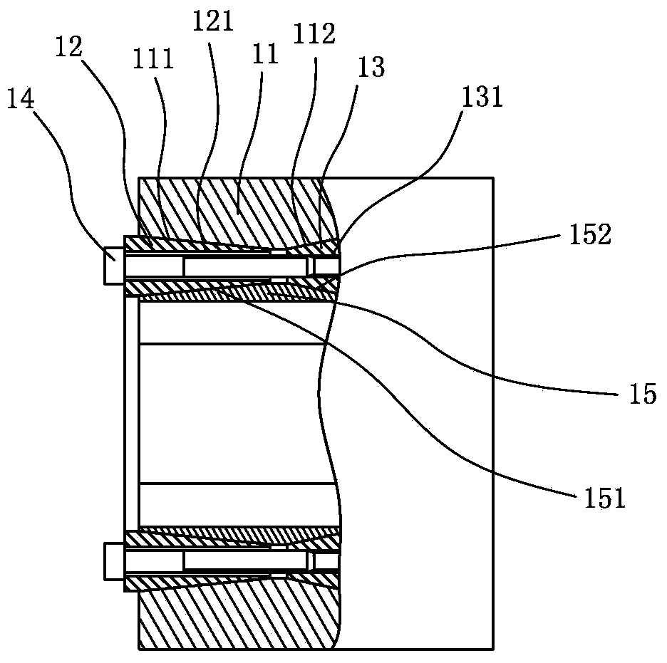
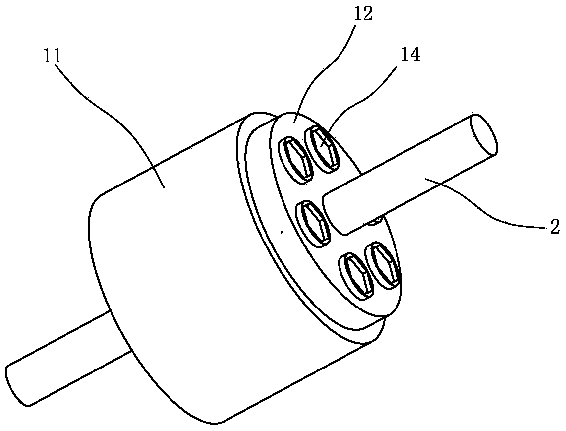
The invention provides an axial shiftable type abrasive wheel and an intelligent adjustment device of the axial shiftable type abrasive wheel. The abrasive wheel is adjustably arranged on a spindle and comprises a cylindrical abrasive wheel body, an elastic locking sleeve and a tightening mechanism, wherein the elastic locking sleeve is movably arranged on the spindle, and the tightening mechanism is arranged between the abrasive wheel body and the elastic locking sleeve. Two conical inner walls are formed on the abrasive wheel body, two conical outer walls opposite to the conical inner walls are formed on the elastic locking sleeve, and two wedge-shaped grooves are formed between the two conical inner walls and the two conical outer walls, wherein openings of the two wedge-shaped grooves are formed in the two ends of the abrasive wheel body. The tightening mechanism comprises two wedge-shaped lantern rings and a plurality of bolts, wherein the two wedge-shaped lantern rings are embedded into the two wedge-shaped grooves and can shrink and expand, the bolts are connected between the two wedge-shaped lantern rings, one wedge-shaped lantern ring is provided with through holes which are transversely through and allow the bolts to penetrate through, the other wedge-shaped lantern ring is provided with screw holes matched with the bolts, the two wedge-shaped lantern rings can be driven to move oppositely by screwing up the bolts, the wedge-shaped lantern rings expand under the effect of the wedge-shaped grooves to apply radial force to the elastic locking sleeve, and then the elastic locking sleeve clasps the spindle.

Description

technical field [0001] The invention relates to an axially variable grinding wheel and an intelligent adjustment device thereof. Background technique [0002] At present, workpieces that require high surface precision need to be ground, and the most widely used tool for grinding is the grinding wheel. Due to the working position of the grinding wheel, either fixed or at a certain angle to the surface to be processed, the wear of the working surface of the grinding wheel is often uneven. Traditionally, on the surface of the same normal working grinding wheel, after a period of use, it is found that a certain area has a large amount of wear, resulting in the subsequent machining process not meeting the required machining accuracy requirements; and under the same circumstances, another or several other Areas with less wear can continue to be used for machining, in which case the entire wheel must be replaced to meet machining needs. The above two situations not only increase ...

Claims


Application Information

Patent Timeline
IPC IPC(8): B24B41/04
CPCB24B41/04
Inventor 陈秋平陈晓龙顾立志瞿少魁
Owner QUANZHOU SHUANGYANG DIAMOND TOOL
Learn More