
Vacuum suction sucker

A technology of vacuum suction and fixing plate, applied in the direction of chucks, manipulators, manufacturing tools, etc., can solve the problems of low work efficiency, low equipment utilization, increase production costs, etc., and achieve convenient replacement, high precision, and interchangeability. strong effect

Inactive Publication Date: 2014-04-09
BOZHON PRECISION IND TECH CO LTD
View PDF0 Cites 3 Cited by
  • Summary
  • Abstract
  • Description
  • Claims
  • Application Information

AI Technical Summary

Problems solved by technology

[0002] When attaching and assembling small electronic components, plastic parts, iron sheets, protective films and other products, these small parts need to be sucked by vacuum, and the sucked parts need to be transported to the standard operating position for operation. The existing technology Generally, the suction head can only pick up one part at a time, so the work efficiency is low, the equipment utilization rate is low, and the production cost is increased.

Method used


Image

  • Vacuum suction sucker
  • Vacuum suction sucker
  • Vacuum suction sucker

Examples


Embodiment Construction

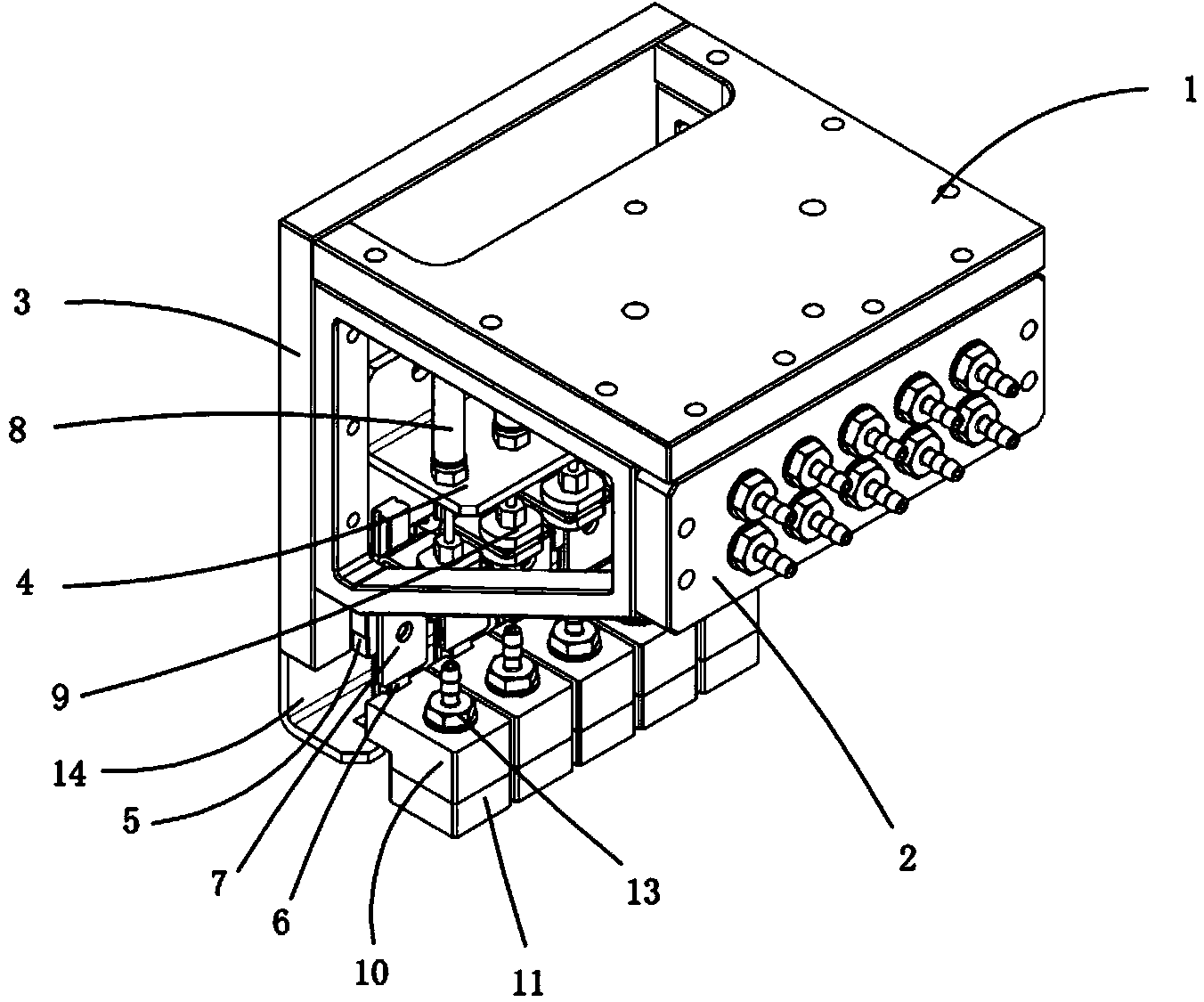
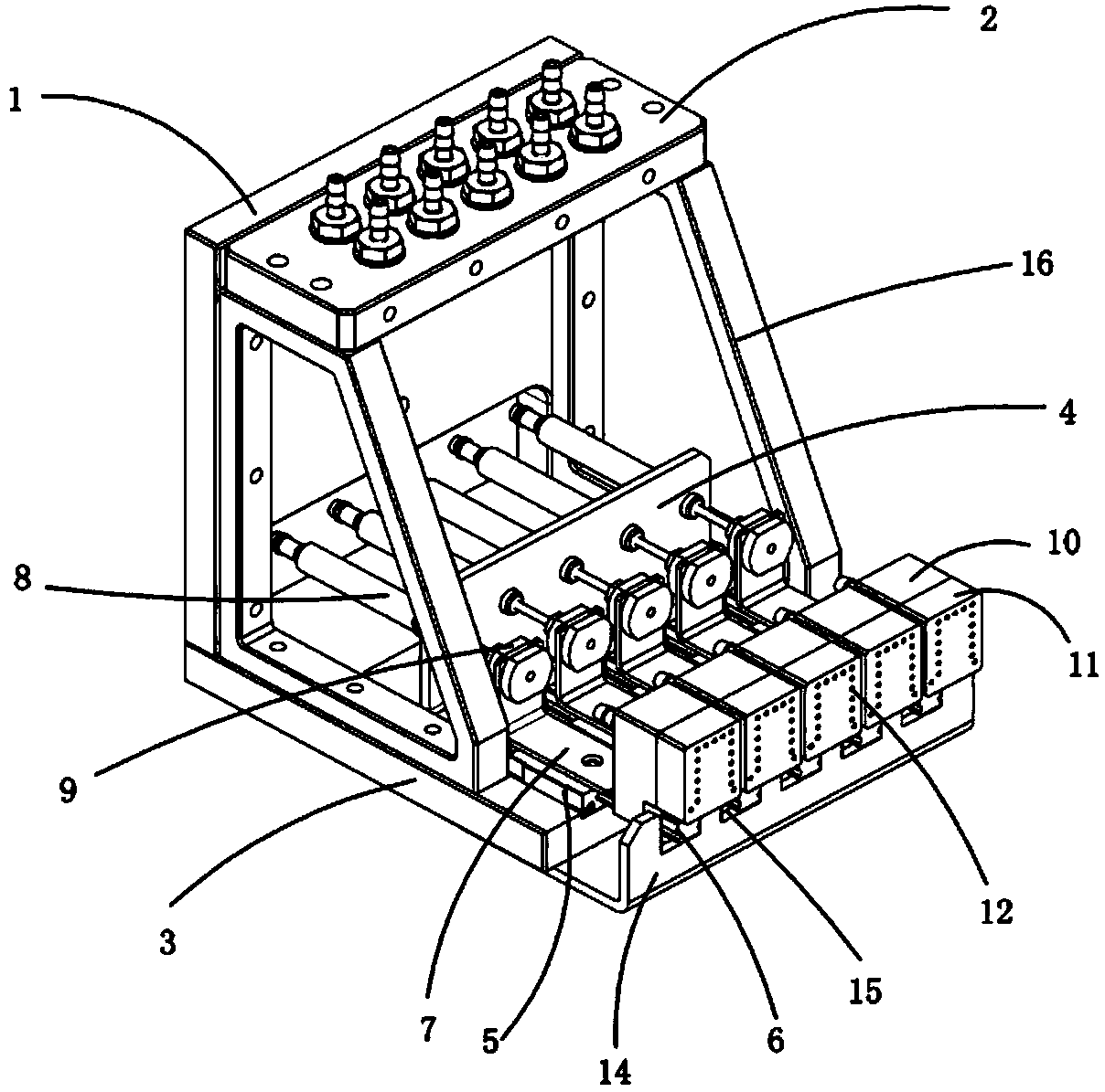
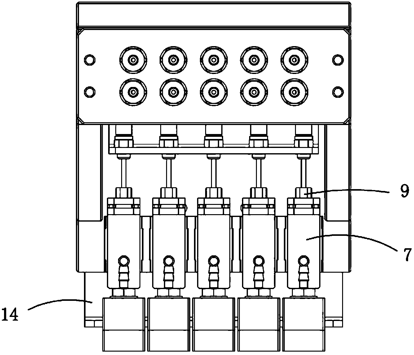
[0021] Examples, see attached Figure 1~4 , a vacuum suction head, which includes a top plate 1, a joint fixing plate 2 is vertically installed on the front side of the top plate, a mini joint is placed on the joint fixing plate, and a slider fixing plate 3 is vertically installed on the rear side of the top plate; The fixed plate of the slider is fixedly connected with a pen-type cylinder fixed sheet metal 4 and four groups of sliders 5, and each group of sliders is equipped with slide rails 6; each group of slide rails is connected with a cylinder connected with sheet metal 7 , four sets of pen-shaped cylinders 8 are connected to the fixed sheet metal of the pen-shaped cylinder, and the lower ends of each set of pen-shaped cylinders are connected with each group of cylinder connecting sheet metal through floating joints 9 respectively; There is a suction head fixing block 10, and the bottom of each group of suction head fixing blocks is equipped with a suction head 11, and t...


PUM


Abstract

The invention relates to a vacuum suction sucker. A connector fixing plate and a sliding block fixing plate ate installed on a top plate of the vacuum suction sucker; a pen-type air cylinder fixing metal plate and four sliding blocks are fixedly connected to the sliding block fixing plate, and sliding rails are installed on each sliding block; an air cylinder connecting metal plate is connected to each sliding rail, four pen-type air cylinders are connected to the pen-type air cylinder fixing metal plate, and the lower ends of the pen-type air cylinders are connected with the air cylinder connecting metal plates respectively through floating connectors; a sucker fixing block is installed below each sliding rail, suckers are installed below each sucker fixing block, and mini connectors are installed on each sucker fixing block; a limiting metal plate is connected to the lower portion of the sliding block fixing plate; a mechanical arm is installed on the top plate and driven to the position above products in a supplying area; the pen-type air cylinders are ventilated, the sucker is extended out to the limiting metal plate, it is guaranteed that the bottom faces of the four suckers are flush, the suckers suck air to suck the products, and then the pen-type air cylinders are retracted; the mechanical arm is then driven to move to an attachment area or an assembly area, and the suckers are extended out one by one to enable the products to be attached or assembled to the specific positions.

Description

Technical field: [0001] The invention relates to a vacuum suction head. Background technique: [0002] When attaching and assembling small electronic components, plastic parts, iron sheets, protective films and other products, these small parts need to be sucked by vacuum, and the sucked parts need to be transported to the standard operating position for operation. The existing technology Generally, the suction head can only pick up one part at a time, so the work efficiency is low, the equipment utilization rate is low, and the production cost is increased. Invention content: [0003] The purpose of the present invention is to provide a vacuum suction head for the deficiencies of the prior art, which can absorb multiple regularly arranged products at the same time, and each product can move up and down independently to perform operations such as attachment and assembly. It improves equipment utilization and reduces costs. [0004] Technical solutions of the present inve...

Claims


Application Information

Patent Timeline
Patent Type & Authority Applications(China)
IPC IPC(8): B25J15/06
Inventor 吕绍林蔡志敏侯教东雷海涛张文生
Owner BOZHON PRECISION IND TECH CO LTD
Learn More