Planar flexible beam unit

A flexible beam and plane technology, which is applied in the direction of rotorcraft, motor vehicles, aircraft, etc., can solve the problems of complex manufacturing of torsion and bending beams, and achieve the effect of lightweight design

Inactive Publication Date: 2014-04-09
AIRBUS HELICOPTERS DEUT GMBH
View PDF6 Cites 5 Cited by
  • Summary
  • Abstract
  • Description
  • Claims
  • Application Information

AI Technical Summary

Problems solved by technology

The fabrication of twiste...

Method used


Image

  • Planar flexible beam unit
  • Planar flexible beam unit
  • Planar flexible beam unit

Examples


Embodiment Construction

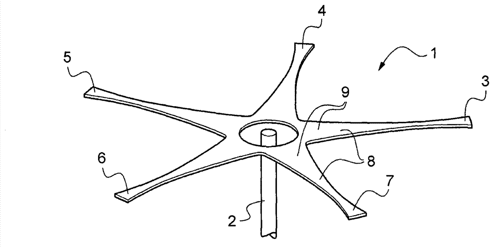
[0032] according to figure 1 , the planar flexible beam unit 1 is centered on the rotor shaft 2 of the multi-bladed main rotor (not shown) of the helicopter. The planar flexbeam unit 1 comprises a concentric hub (not shown) and generally planar five torque arms 3-7 projecting radially from the center and having a generally circular opening. The five torque arms 3-7 are equiangularly spaced. The planar flexible beam unit 1 is made of composite compound.

[0033] Each torque arm 3-7 has a generally inner arc surface 8 on each side of its radial extension, at the root region 9 of said torque arm 3-7 is integral with its adjacent torque arm 3-7, and has Relatively large width, so that the thickness / width ratio is less than 1:3. The thickness is defined perpendicular to the planar flexible beam unit 1 and the width corresponds to the respective extensions of the torque arms 3-7 in their chord direction.

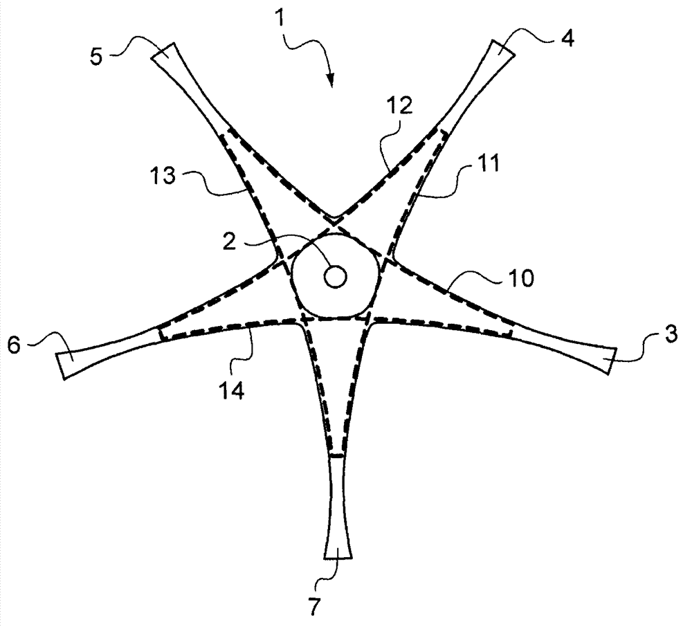
[0034] Such as figure 2 As shown, the corresponding features are used...


PUM


Abstract

A planar flexible beam unit (1, 40) used for the multi-blade main rotor of a helicopter is an interface between a rotor shaft (2) and the multi-blade main rotor. The planar flexible beam unit (1, 40) comprises a plurality of roughly-planar torque arms (3-7, 41-46), each of the torque arms (3-7, 41-46) has a roughly-concave arc-shaped surface (8) along its radial extension portion, and forms an integral body with its adjacent torque arm (3-7, 41-46). Each of the torque arms (3-7, 41-46) comprises two roughly-straight unidirectional fiber bundles (10-14) obtained through the agglomeration of hard synthetic resin and arranged along the roughly-concave arc-shaped surface (8) of its radial extension portion. Each of the fiber bundles penetrates into two roughly-opposite torque arms (3-7, 41-46), and has no substantial direction change.

Description

technical field [0001] The invention relates to a planar flexible beam unit having the features of claim 1 . Background technique [0002] A helicopter rotor system secures and supports the helicopter blades to the engine output shaft and includes, but is not limited to, a hub mounted on the output shaft and a set of spindles or yokes that attach the blades to the hub. The rotor system must withstand the enormous centrifugal forces exerted by the blades as they spin while allowing them to flap, pitch and shimmy. Several different systems for this task are variations of the basic design, called articulated and bearingless or hingeless. The articulation system uses a rigid spindle equipped with hinges and bearings for the aforementioned blade movement. Bearingless systems consist of a special composite mandrel, known as a flexbeam, that is flexible enough to twist to allow the blade to move without bearings and additional mechanisms. For hingeless rotors, the function of di...

Claims


Application Information

Patent Timeline
IPC IPC(8): B64C27/33
Inventor B·恩恩克尔R·普法勒尔
Owner AIRBUS HELICOPTERS DEUT GMBH
Why Eureka
Try Eureka