
Tubular flow pump with partially adjustable guide vane body

A technology of guide vanes and tubular pumps, applied to pumps, components of pumping devices for elastic fluids, pump elements, etc., can solve the problems of water pump efficiency decline, angle difference, impact, etc., and achieve accurate adjustment angles, Adjustment speed is fast and the effect of improving efficiency

Inactive Publication Date: 2016-02-24
CHINA AGRI UNIV
View PDF3 Cites 0 Cited by
  • Summary
  • Abstract
  • Description
  • Claims
  • Application Information

AI Technical Summary

Problems solved by technology

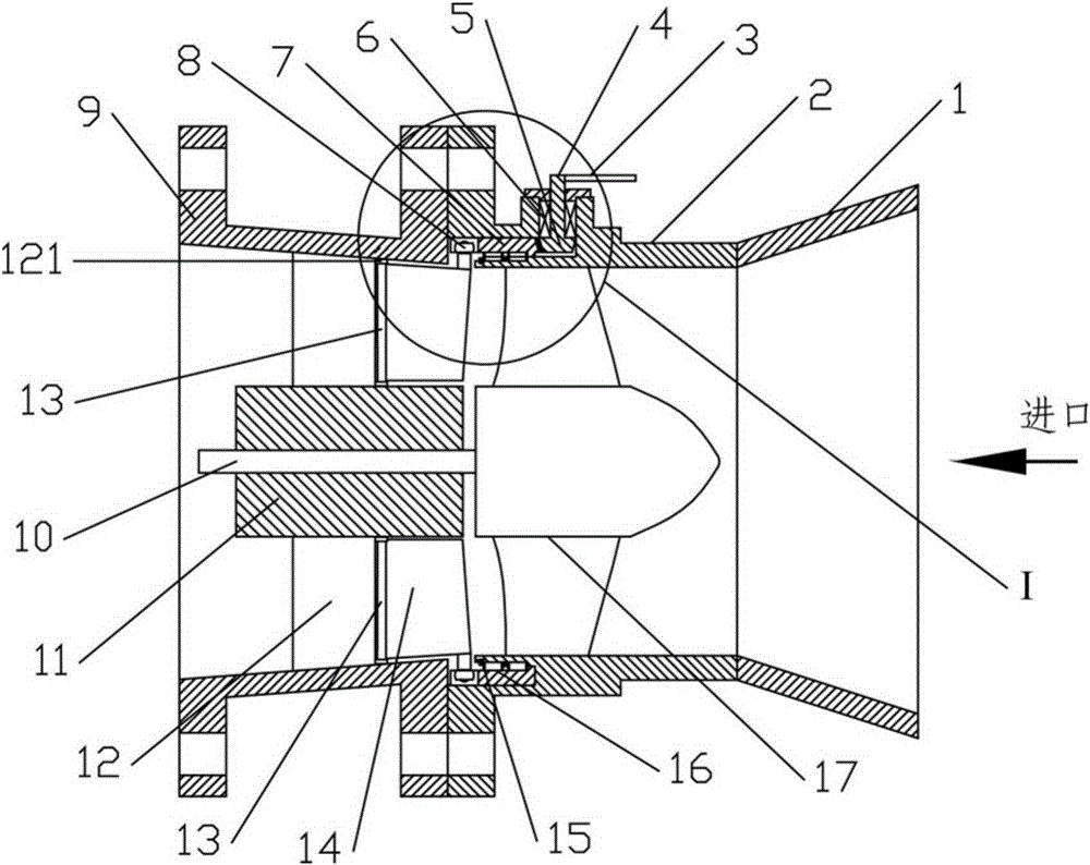
[0006] The guide vane body of the traditional tubular pump is fixedly installed outside the guide vane body hub of the pump shaft, the guide vane body is evenly arranged, and the geometric shape and placement angle of each blade are the same; the guide vane body inlet is connected with the impeller outlet, and the outlet It is connected with the outlet pipeline; when the pump is running at a non-rated operating point, there is an angle difference between the placement angle of the guide vane body and the liquid flow angle at the outlet of the impeller, which will cause impact, reduce the efficiency of the pump, and reduce economic and social benefits

Method used


Image

  • Tubular flow pump with partially adjustable guide vane body
  • Tubular flow pump with partially adjustable guide vane body
  • Tubular flow pump with partially adjustable guide vane body

Examples


Embodiment 1

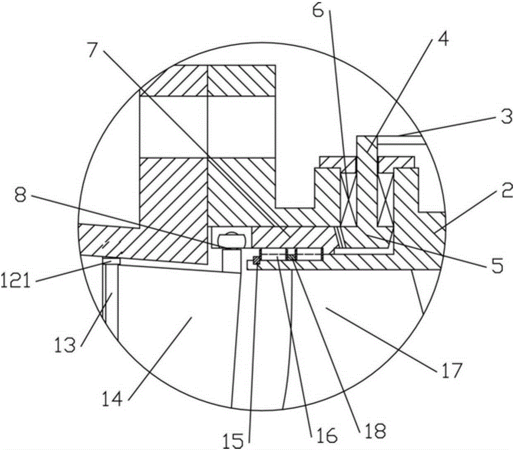
[0030] like figure 1 and 2 As shown, the tubular flow pump of the present invention includes a water inlet pipe 1, an outlet pipe 9, an impeller chamber 2, an impeller 17, a pump shaft 10, a guide vane body hub 11, five guide vane bodies and a regulating device, and a water inlet pipe 1 and a horn Formed into a round pipe, the impeller chamber 2 is a round pipe with both ends connected. Preferably, the impeller chamber 2 is formed by connecting multiple sections of round pipes through flanges. The water inlet pipe 1 is fixed at the front end of the impeller chamber 2, and the outlet pipe 9 is fixed at the rear end of the impeller chamber 2; the guide vane hub 11 is arranged at the center of the impeller chamber 2, and extends toward the water outlet pipe 9 along the axial direction of the impeller chamber 2 The pump shaft 10 is rotatably installed in the guide vane hub 11, and the impeller is fixed at the end of the pump shaft 10 near the inlet pipe 1; the fixed part 12 is fi...

Embodiment 2

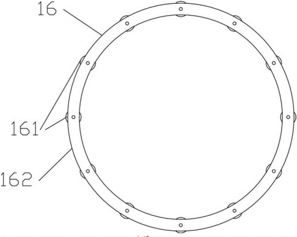
[0040] This embodiment is basically the same as Embodiment 1, except that a circle of rolling elements 16 is used in this embodiment.


PUM


Abstract

The invention relates to the field of water pumps and discloses a tubular pump with part of a guide vane body being adjustable. The tubular pump comprises a water inlet pipe, a water outlet pipe, an impeller chamber, an impeller, a pump shaft, a guide vane body hub, a guide vane body and an adjusting device. The water inlet pipe is fixed at the front end of the impeller chamber. The water outlet pipe is fixed at the rear end of the impeller chamber. The guide vane body hub is disposed at the center of the impeller chamber. The pump shaft is rotatably mounted in the guide vane body hub. The impeller is fixed at one end, close to the water inlet pipe, of the pump shaft. The guide vane body comprises a fixed part and a movable part which are hinged to each other. The adjusting device drives the movable part to rotate around the hinged part of the movable part and the fixed part through a rotary ring and a knuckle, and accordingly the inlet angle of the guide vane body is changed, the angle difference between the guide vane body placing angle and the impeller outlet liquid flow angle, and the efficiency of water pumps under non-rated conditions is increased.

Description

technical field [0001] The invention relates to the field of water pumps, in particular to a through-flow pump with partially adjustable guide vanes. Background technique [0002] Tubular flow pumps are widely used in drainage and irrigation fields, and are characterized by large flow and low head. [0003] About 1 / 3 of the electricity in the modern power industry is used to drive vane pumps. Tubular pumps are a type of vane pumps, and the improvement of their efficiency has direct significance for reducing energy consumption. [0004] The improvement of the efficiency of a tubular pump not only depends on the performance of the impeller, but also is closely related to the shape of the inlet and outlet channels of the pump and the flow-passing parts. relationship, the efficiency of the pump device can achieve the optimum value. [0005] Due to the high-speed rotation of the impeller of the tubular pump, the absolute velocity of the impeller outlet has a peripheral velocity...

Claims


Application Information

Patent Timeline
Patent Type & Authority Patents(China)
IPC IPC(8): F04D29/18
Inventor 唐学林丁鹏王福军唐雨萌
Owner CHINA AGRI UNIV
Learn More