Sealing system for a solenoid valve and solenoid valve

A technology of sealing system and magnetic valve, which is applied in the direction of valve operation/release device, parts in contact between valve element and valve seat, valve lift, etc., which can solve problems such as block movement and difficulty in magnetic core movement, and prevent The effect of falling off and reducing the contact surface

Active Publication Date: 2014-04-09
BURKERT WERKE
View PDF6 Cites 2 Cited by
  • Summary
  • Abstract
  • Description
  • Claims
  • Application Information

AI Technical Summary

Problems solved by technology

However, highly viscous media makes movement of the core difficult and hinders movement
[0005] In addition, the use of highly viscous media in these valves is problematic, namely that

Method used


Image

  • Sealing system for a solenoid valve and solenoid valve
  • Sealing system for a solenoid valve and solenoid valve
  • Sealing system for a solenoid valve and solenoid valve

Examples


Embodiment Construction

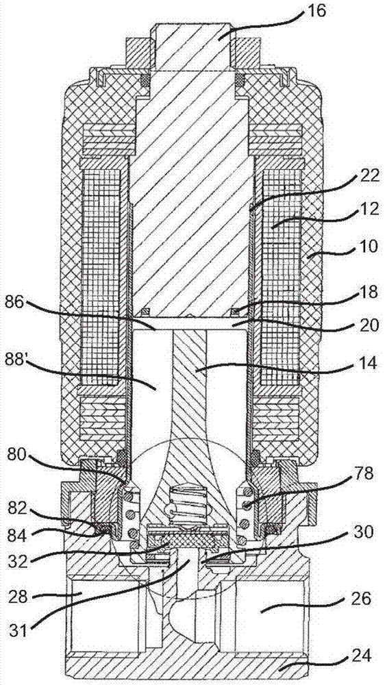
[0043] exist figure 1 shows a solenoid valve through which highly viscous oil flows and which is used to meter the oil in the fuel injector.

[0044] The solenoid valve comprises a housing 10 with an electrical coil 12 for displacing an actuating element 14 , which in the present case is designed as a magnetic core. In the following, however, for the sake of simplicity, the magnetic core is always referred to as the operating element. The operating element 14 is movable in the axial direction via the coil 12 .

[0045] In the interior of the housing 10 there is a cavity which is also partially surrounded by the coil 12 and which is closed in the axial direction by a plug 16 made of ferromagnetic material. When the solenoid valve is driven with alternating voltage, an alternating voltage ring 18 made of copper or silver is installed in the plug 16 at the end side.

[0046] The actuating element 14 is placed in a so-called valve chamber which is partially filled by the actuatin...


PUM


Abstract

A sealing system for a solenoid valve is provided for accommodation in a recess in an actuating element movable by a coil. The recess proceeds from an end face of the actuating element close to a valve seat. The actuating element is movably mounted in a solenoid valve and designed to clear or close the valve seat (30). A sealing disk and a spring element biasing the sealing disk are provided, wherein the spring element is arranged on the end face facing away from the valve seat centered with respect to the sealing disk and exerts a force on the sealing disk in direction of the valve seat. The sealing disk is axially shiftably guided in the actuating element. A solenoid valve itself includes such sealing system.

Description

technical field [0001] The invention relates to a sealing system for a magnetic valve. Furthermore, the invention relates to a magnetic valve. Background technique [0002] The sealing system according to the invention is especially intended for the use of highly viscous oils in fuel injectors. [0003] Solenoid valves for metering oil to fuel injectors place high demands on them. Typical conditions are a medium pressure in the range of 30 bar, a coil temperature of about 165° C. in the case of oil with a viscosity of about 75 cst. [0004] In the case of a pressure of 30 bar, it is not possible to use a valve with a diaphragm separating the medium. This means that when the valve is switched, the valve chamber in which the magnetic core moves is filled with medium and the magnetic core and the sealing system are flushed with oil. During the switching process, when the magnetic core is withdrawn, it must force the oil out of the valve chamber. However, highly viscous med...

Claims


Application Information

Patent Timeline
IPC IPC(8): F16K1/34F16K1/46F16K31/06
CPCF16K31/0655F16K31/10F16K25/005F16K31/0658F16K25/04
Inventor 阿尔弗雷德·莱迪格
Owner BURKERT WERKE
Why Eureka
Try Eureka