
The jacking system and jacking method for the prefabricated construction of pipe joints by factory method

A factory method, jacking technology, applied in pipeline laying and maintenance, pipes/pipe joints/fittings, machinery and equipment, etc., can solve the design of cumbersome and complex jacking mechanism and jacking beam reaction force seat, inconvenient turning section pipe joints The construction and construction conditions are difficult to meet and other problems, so as to ensure the quality of the jacking construction, reduce the risk of the jacking construction, and improve the efficiency of the jacking construction.

Active Publication Date: 2016-11-02
CCCC FOURTH HARBOR ENG CO LTD +3
View PDF5 Cites 0 Cited by
  • Summary
  • Abstract
  • Description
  • Claims
  • Application Information

AI Technical Summary

Problems solved by technology

For the super-large prefabricated immersed tubes constructed by the factory method in the world, the jacking operation basically adopts two ideas: centralized jacking and multi-point decentralized synchronous jacking; the centralized jacking scheme requires the design of heavy and complicated jacking mechanisms and jacking beams Reaction seat, the actual construction conditions are difficult to meet, and it is inconvenient to carry out pipe joint construction in the turning section (because of the pipe joint jacking in the curved section); decentralized jacking has the advantages of simple jacking structure, uniform distribution of pipe joint jacking force and steel structure Controllable cost and other advantages; however, the current decentralized jacking construction is not yet perfect

Method used


Image

  • The jacking system and jacking method for the prefabricated construction of pipe joints by factory method
  • The jacking system and jacking method for the prefabricated construction of pipe joints by factory method
  • The jacking system and jacking method for the prefabricated construction of pipe joints by factory method

Examples


Embodiment Construction

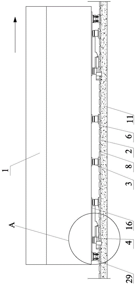
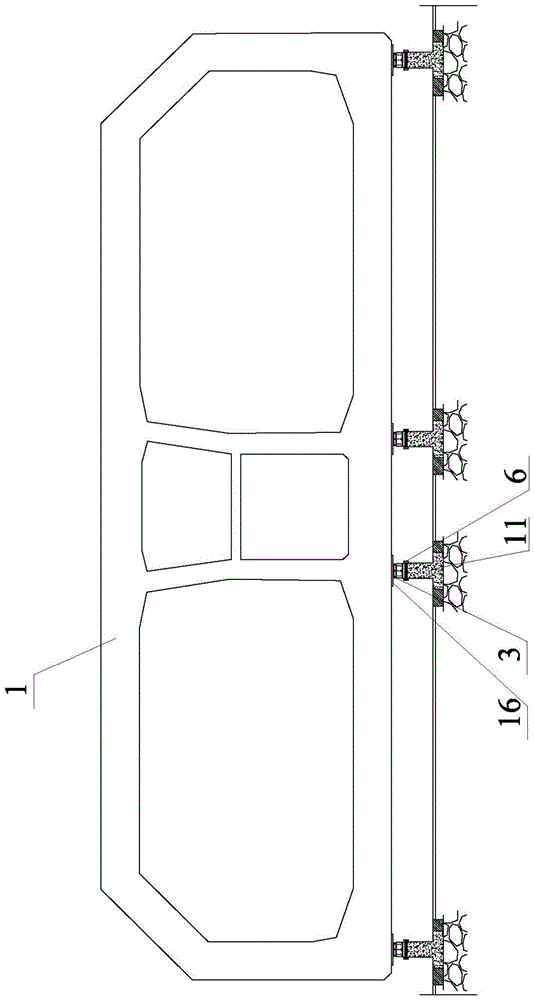
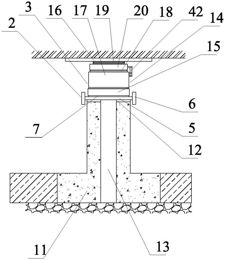
[0048] see figure 1 (The direction of the arrow is the pushing direction of the pipe joint), figure 2 , image 3 Figure 4 , Figure 5 , Figure 6As shown, the jacking system for the prefabricated construction of the pipe joint in the factory method of the present invention includes a plurality of slide rails 2 arranged in parallel for realizing the horizontal displacement of the pipe joint 1, and a plurality of sliding rails 2 for the overall support of the pipe joint. The supporting device 3, a plurality of pushing devices 4 for pushing the pipe joints, and a general control device for overall control of the pushing system work; the slide rail is arranged under the pipe joints and arranged along the length direction of the pipe joints The support device is correspondingly arranged in the slide rail, the upper end of the support device is fixedly connected to the bottom end of the pipe joint, the lower end is slidably connected to the slide rail, and arranged in sequence...


PUM


Abstract

The invention relates to a pushing system and method of factory method segment prefabrication segment prefabrication construction, in particular to a pushing system capable of supporting a segment through multiple points dispersedly and pushing synchronously through a sliding rail, a supporting device and a pushing device, and a pushing method using the pushing system. The pushing system comprises the sliding rails, the supporting device, the pushing device and a main controlling device. The sliding rail is arranged below the segment, the upper end of the supporting device is fixedly connected to the bottom end of the segment, and the lower end is connected to the sliding rail in a sliding manner; the pushing device is arranged on the sliding rail and is hinged to the bottom end of the segment; the main controlling device is connected to the supporting device and the pushing device. The pushing system adopts the design of the supporting device, the segment can be supported through multiple joints, pressure of each supporting joint at the bottom end of the segment is balanced accordingly, so that the segment is prevented from deforming and cracking in the pushing process, pushing construction quality is guaranteed, and pushing construction risks are reduced.

Description

technical field [0001] The present invention relates to a jacking system and a jacking method for the prefabricated construction of pipe joints by the factory method, in particular to a jacking system that realizes multi-point support for pipe joints and synchronously dispersed jacking through slide rails, support devices and jacking devices And the pushing method realized by applying the pushing system. Background technique [0002] At present, the prefabrication of super-large immersed tubes basically adopts two construction ideas: factory method and dry dock method. [0003] Due to the long turnaround period of construction equipment in the dry dock method, which cannot meet the requirements of the construction period, the factory method construction plan is often used. The basic idea of ​​​​this kind of plan is to produce and construct on the assembly line to improve efficiency. [0004] Shorten the construction period. For the super-large prefabricated immersed tubes ...

Claims


Application Information

Patent Timeline
Patent Type & Authority Patents(China)
IPC IPC(8): F16L1/024
CPCF16L1/024F16L1/10
Inventor 林鸣尹海卿翟世鸿杨凯梁杰忠陈伟彬张文森李磊胡利文伍绍博
Owner CCCC FOURTH HARBOR ENG CO LTD
Learn More